Motion video output for multiple displays

a technology of motion video and multiple displays, applied in the field of digital cameras, can solve the problems of unsatisfactory effects of images displayed on displays, unnatural and unrealistic appearance, and less desirable hue twisting, so as to reduce highlights, narrow the brightness range, and reduce highlights.

Active Publication Date: 2017-03-09
RED COM LLC
View PDF9 Cites 30 Cited by
  • Summary
  • Abstract
  • Description
  • Claims
  • Application Information

AI Technical Summary

Benefits of technology

[0003]In some embodiments, an image data processing system is disclosed. The image data processing system can include one or more processors, a first video output port, and a second video output port. The one or more processors can: receive an encoded stream of digital motion picture image data derived from digital image data captured with an image sensor, the encoded stream having been encoded using an encoding function; generate a first monitoring data stream from the encoded stream using a first decoding function, the first monitoring data stream including first image data, the first decoding function being an inverse of the encoding function; and generate a second monitoring data stream from the encoded stream using a second decoding function different from the first decoding function, the second monitoring data stream including second image data having a narrower brightness range than the first image data. The first video output port can be in communication with the one or more processors, and the first video output port can output the first monitoring data stream for display. The second video output port can be in communication with the one or more processors, and the second video output port can output the second monitoring data stream for display in parallel with the first video output port outputting the first monitoring data stream.
[0004]The image data processing system of the preceding paragraph can further include one or more of the following features: The first video output port can output the first monitoring data stream for live monitoring on a high dynamic range display and the second video output port can output the second monitoring data stream for live monitoring on a standard dynamic range display. The one or more processors can generate the first monitoring data stream and the second monitoring data stream while the image sensor captures the digital image data. The second decoding function can diminish highlights in the encoded stream more than the first decoding function for tones brighter than middle grey. The encoding function can be a log function, and the first decoding function can be an inverse log function. A first segment of the second decoding function can follow a non-linear function. For a plurality of inputs, the first segment can generate outputs that are less than outputs generated by the first decoding function. The first segment can follow an inverse power law function. The inverse power law function can be of a form y=f(x)c, and c can be a value ranging from between 1.5 to 1.6. A second segment of the second decoding function can follow a linear function, and the second segment and the first segment can be connected in the second decoding function at a location of a mapping for a tone of middle grey. A second segment of the second decoding function can follow an inverse power law function, and the second segment and the first segment can be connected in the second decoding function at a location of a mapping for a tone of middle grey. The encoded stream can have been graded according to one or more grading parameters prior to generating the first monitoring data stream and the second monitoring data stream from the encoded stream, and the one or more grading parameters can include one or more of a saturation adjustment parameter, a white balance adjustment parameter, a lift adjustment parameter, a gamma adjustment parameter, a gain adjustment parameter, a shadow adjustment parameter, and a highlight adjustment parameter. The one or more processors can store in a memory device (i) the digital motion picture image data before or after compression and (ii) the one or more grading parameters used to grade the encoded stream. The one or more processors can: receive a user input via a user interface; change at least one of the one or more grading parameters according to the user input; generate the first monitoring data stream so that first images displayed on a first display visually reflect changing of the at least one of the one or more grading parameters according to the user input, the first images produced on the first display from the first monitoring data stream; and generate the second monitoring data stream so that second images displayed on a second display visually reflect changing of the at least one of the one or more grading parameters according to the user input, the second images produced on the second display from the second monitoring data stream. The image data processing system can further include a camera housing and the image sensor, and the camera housing can support the first video output port and the second video output port and contain the one or more processors and the image sensor, and the image sensor can convert light incident on the image sensor into the digital image data. The image data processing system can further include a port extender housing, the port extender housing being releasably attachable to a camera housing, the port extender housing supporting the first video output port and the second video output port and containing the one or more processors, the camera housing containing the image sensor, the image sensor being configured to convert light incident on the image sensor into the digital image data. The one or more processors can generate the encoded stream from the digital motion picture image data using the encoding function. The one or more processors can: generate the first monitoring data stream by linearizing the encoded stream using the first decoding function; and generate the second monitoring data stream by linearizing the encoded stream using the second decoding function.
[0005]In some embodiments, an image data display method is disclosed. The image data display method can be performed under control of one or more processors. The image data display method can include: receiving an encoded stream of digital motion picture image data derived from digital image data captured with an image sensor, the encoded stream having been encoded using an encoding function; generating a first monitoring data stream from the encoded stream using a first decoding function, the first monitoring data stream including first image data, the first decoding function being an inverse of the encoding function; generating a second monitoring data stream from the encoded stream using a second decoding function different from the first decoding function, the second monitoring data stream including second image data having a narrower brightness range than the first image data; outputting, via a first video output port, the first monitoring data stream for display; and outputting, via a second video output port, the second monitoring data stream for display in parallel with said outputting the first monitoring data stream.
[0006]The image data display method of the preceding paragraph can further include one or more of the following features: The outputting the first monitoring data stream can include outputting the first monitoring data stream for live monitoring on a high dynamic range display, and the outputting the second monitoring data stream can include outputting the second monitoring data stream for live monitoring on a standard dynamic range display. The second decoding function can diminish highlights in the encoded stream more than the first decoding function for tones brighter than middle grey. The image data display method can further include: under control of the one or more processors: grading the encoded stream according to one or more grading parameters prior to the generating the first monitoring data stream and the generating the second monitoring data stream. The image data display method can further include: under control of the one or more processors: receiving a user input via a user interface; and changing one or more grading parameters according to the user input, the one or more grading parameters being used to grade the encoded stream, wherein the generating the first monitoring data stream can include generating the first monitoring data stream so that first images displayed on a first display visually reflect changing of the one or more grading parameters according to the user input, the first images produced on the first display from the first monitoring data stream, and wherein the generating the second monitoring data stream can include generating the second monitoring data stream so that second images displayed on a second display visually reflect changing of the one or more grading parameters according to the user input, the second images produced on the second display from the second monitoring data stream. The image data display method can further include: under control of the one or more processors: generating the encoded stream from the digital motion picture image data using the encoding function.

Problems solved by technology

The difference between the brightness capture ranges of camera systems and brightness display ranges of displays can cause undesirable effects in images displayed on displays.
As a result, some bright portions of the image may saturate at a brightest display level of the display and take on an unnatural and unrealistic appearance.
The hue twisting can be less desirable, in some instances, when impacting colors in the skin-tone region or sunsets and the like.
As HDR, in some instances, doesn't benefit from this kind of roll-off (it may benefit from it's own different kind of roll-off, but at much brighter image values), the lack of pure linearity below mid grey may cause a slight image difference.
Driving the highlight protection directly off the calculated extent data can be effective, but can make the development curve specifically dependent upon matrix settings which may not be desirable in some cases.

Method used


Image

  • Motion video output for multiple displays
  • Motion video output for multiple displays
  • Motion video output for multiple displays

Examples


first example

Camera System

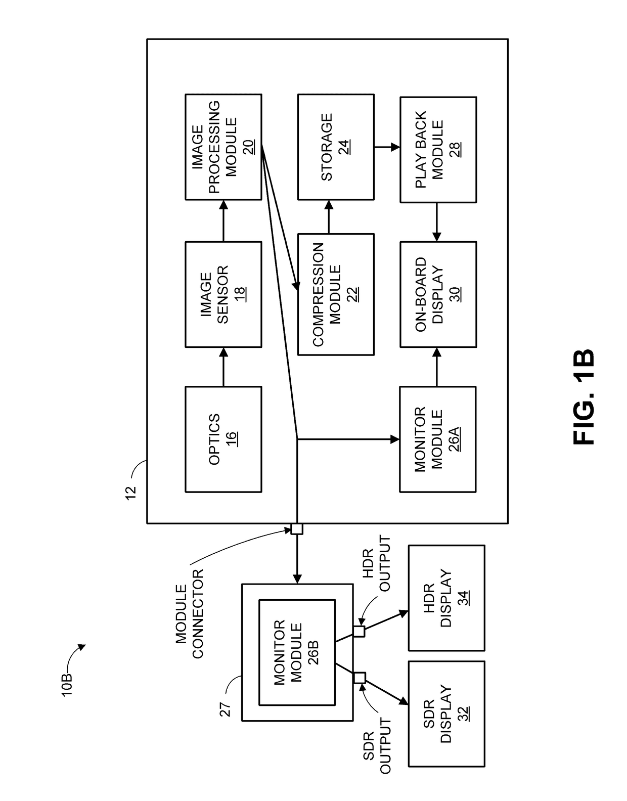
[0081]FIG. 3A is a perspective view of a front of a brain module 100 of a modular camera system. The brain module 100 can include a housing 102 (sometimes referred to as a body) that contains and supports the components of the brain module 100. The brain module 100 can be an example implementation of the camera 12 of FIG. 1B. More details about a brain module, such as the brain module 100, and related camera components are provided in U.S. patent application Ser. No. 15 / 094,693, entitled “MODULAR MOTION CAMERA,” filed Apr. 8, 2016, which is incorporated by reference herein in its entirety.

[0082]The housing 102 can include one or more top surface interfaces for mechanically or electrically coupling one or more modules to a top of the housing 102. One of the top surface mounting interfaces can include a first module connector 110 and mounting holes 112A, 112B for electrically and mechanically coupling a module, such as a display module (for instance, a liquid-crystal disp...

second example

Camera System

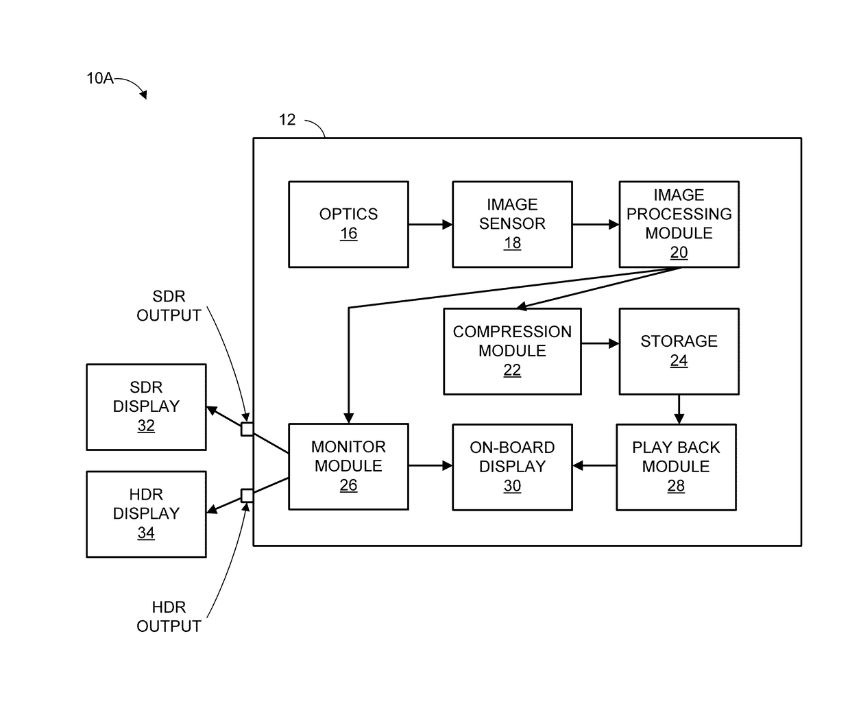
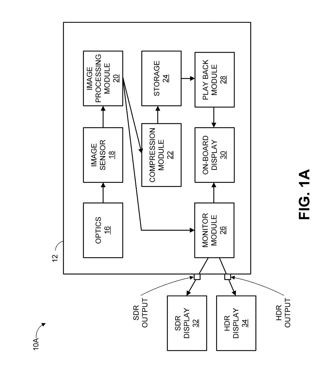
[0096]FIG. 5A is a front perspective view of a brain module 512 of a modular camera system releasably coupled with a lens mount module 514 and a lens 516. FIG. 5B is a back perspective view of the brain module 512 releasably coupled with the lens mount module 514 and the lens 516. The brain module 512 can be an example implementation of the camera 12 of FIG. 1A or FIG. 1B. The brain module 512 can include various connectors 501 for providing data input or output. In various embodiments, such connectors 501 include a SDR output (such as described with respect to FIG. 1A), a HDR output (such as described with respect to FIG. 1A), one or more video (e.g., HDMI, BNC), audio in and out, data or power connectors. The brain module 512 can include one or more controls such as a power button 502. An interface 548 can be releasably engageable with the brain module 512. The brain module 512 can include an expansion interface 538 mechanically and electrically connectable to other o...

third example

Camera System

[0098]A system can include one or more processors a first video output port, and a second video output port. The one or more processors can: receive digital image data encoded using an encoding function and graded according to one or more grading parameters; generate a first signal from the digital image data using a first decoding function, the first decoding function being an inverse of the encoding function; and generate a second signal from the digital image data using a second decoding function different from the first decoding function. The first video output port can provide the first signal for delivery to a first display. The second video output port can provide the second signal for delivery to a second display.

[0099]The system of the preceding paragraph can include one or more of the following features: The system can include a camera housing and an image sensor, and the image sensor can be contained within the camera housing and configured to convert light i...


PUM


Abstract

An image data processing system can include one or more processors, a first video output port, and a second video output port. The one or more processors can: receive an encoded stream of digital motion picture image data encoded using an encoding function; generate a first monitoring data stream from the encoded stream using a first decoding function, the first monitoring data stream including first image data; and generate a second monitoring data stream from the encoded stream using a second decoding function different from the first decoding function, the second monitoring data stream including second image data having a narrower brightness range than the first image data. The first and second video output ports can output the first and second monitoring data streams for display in parallel.

Description

CROSS-REFERENCE TO RELATED APPLICATIONS[0001]This application claims benefit under 35 U.S.C. §119(e) to U.S. Provisional Patent Application No. 62 / 216,320, filed Sep. 9, 2015. The entire contents of the foregoing application are hereby incorporated by reference.BACKGROUND[0002]The present disclosure is related to digital cameras, such as those for capturing still or moving pictures.SUMMARY[0003]In some embodiments, an image data processing system is disclosed. The image data processing system can include one or more processors, a first video output port, and a second video output port. The one or more processors can: receive an encoded stream of digital motion picture image data derived from digital image data captured with an image sensor, the encoded stream having been encoded using an encoding function; generate a first monitoring data stream from the encoded stream using a first decoding function, the first monitoring data stream including first image data, the first decoding fu...

Claims


Application Information

Patent Timeline
Patent Type & Authority Applications(United States)
IPC IPC(8): H04N5/232G09G3/20
CPCH04N5/23293G09G3/2007H04N5/23216G09G2320/0666G09G2320/08G09G2354/00G09G2320/0673G06F3/1423G09G5/10G09G2320/0271G09G5/02G09G2340/02G09G2340/06H04N19/44H04N23/741G06T9/00
Inventor NATTRESS, THOMAS GRAEME
Owner RED COM LLC
Why Eureka
Try Eureka