Sewing machine presser foot

Active Publication Date: 2017-03-16
JANOME CORP
View PDF8 Cites 2 Cited by
  • Summary
  • Abstract
  • Description
  • Claims
  • Application Information

AI Technical Summary

Benefits of technology

The present invention is a sewing machine presser foot dedicated for couch stitching that makes it easier to insert the decorative string into a needle guiding hole and reduces the probability of the already-inserted string detaching from the needle guiding hole. The presser foot has a string guiding groove and a groove covering portion that can be easily deformed to create a gap in which the decorative string can be inserted, allowing for easy and quick insertion of the string. Overall, the invention improves the setup process of couch stitching and enhances the efficiency of the sewing machine.

Problems solved by technology

In this type of presser foot, a decorative string needs to be inserted through the needle guiding hole, and especially when wool yarn or the like is used as the decorative string, inserting the string through the needle guiding hole of the presser foot becomes extremely difficult, because of the fluffiness of the string.
This type of presser foot can make it easier for the decorative string to be inserted into the needle guiding hole of the presser foot, but unfavorably, the decorative string also detaches more easily from the needle guiding hole.

Method used


Image

  • Sewing machine presser foot
  • Sewing machine presser foot
  • Sewing machine presser foot

Examples


second embodiment

[0045]In the second embodiment, since the bent portion is formed at a position near the left end in the left-right direction of the supporting plate portion of the cover member, substantially the entire portion of the supporting plate portion except the left end in the left-right direction floats by being displaced elastically from the supporting portion of the presser foot body. Due to this, the groove covering portion can be more easily displaced in relation to the upper side of the string guiding groove of the pressing portion and the operation of inserting the decorative string can be performed more easily and quickly.

third embodiment

[0046]In the third embodiment, since the string guide is formed at the left end of the groove covering portion of the cover member, in the process of inserting the decorative string into the needle guiding hole, the decorative string makes substantially surface-contact with the string guide. Thus, it is possible to protect the decorative string so that intensive load is not applied to the decorative string especially during the insertion operation.

fourth embodiment

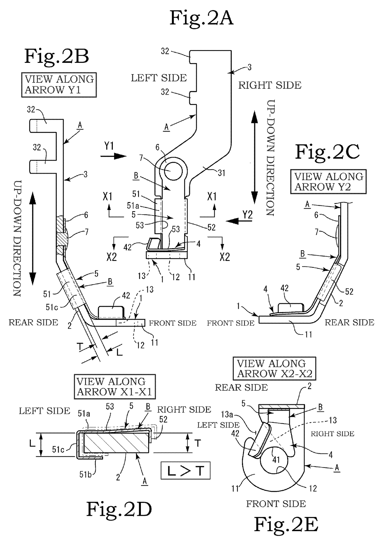
[0047]In the fourth embodiment, the restricting portion which includes the front restricting plate and the rear restricting plate and has a C-shaped cross-sectional shape is formed on the left side in the width direction of the supporting plate portion of the cover member, and the interval between the front restricting plate and the rear restricting plate is larger than the thickness of the supporting portion. Thus, it is possible to restrict a separation distance of the cover member from the supporting portion of the presser foot body, restrict a separation distance of the groove covering portion from the upper surface of the string guiding groove, and prevent deformation resulting from too much displacement.


PUM


Abstract

A sewing machine presser foot includes: a presser foot body including an attachment portion attached to a presser bar of a sewing machine, a supporting portion extending downward from the attachment portion , and a pressing portion in which, at a lower end of the supporting portion, a needle guiding hole having a string guiding groove for guiding a string is formed; and a cover member including a groove covering portion that crosses and covers the string guiding groove of the pressing portion, a supporting plate portion formed along the supporting portion continuously from the groove covering portion, and an attachment portion formed at an end of the supporting plate portion so as to be attached to the presser foot body. A right-side portion of the supporting plate portion of the cover member is fixed to the presser foot body A by the attachment portion.

Description

BACKGROUND OF THE INVENTION[0001]1. Field of the Invention[0002]The present invention relates to a sewing machine presser foot which is attached to a presser bar of the sewing machine and used to sew a decorative string of wool yarn or the like on a cloth, and which makes it easier to pass the decorative string through a needle guiding hole while reducing the probability of the decorative string detaching from the needle guiding hole.[0003]2. Description of the Related Art[0004]Some conventional home sewing machines are designed for what is called “couch stitching”, which is a type of stitching means for sewing decorative wool yarn, embroidery threads, ribbons, etc. on a cloth. A couch stitching operation involves setting an upper thread, a lower thread, and an embroidery frame, passing a third decorative string through a presser foot attached to a sewing machine, and then performing stitching. In this couch stitching operation, a presser foot dedicated for the couch stitching is us...

Claims


Application Information

Patent Timeline
IPC IPC(8): D05B29/02
CPCD05B29/02D05B29/06D05B29/12
Inventor OKADA, MIZUKI
Owner JANOME CORP
Why Eureka
Try Eureka