Stapler

Pending Publication Date: 2022-11-17
ISABERG RAPID
View PDF12 Cites 0 Cited by
  • Summary
  • Abstract
  • Description
  • Claims
  • Application Information

AI Technical Summary

Benefits of technology

The patent describes a device for bending staple legs in a stapling machine. The device has two lever arms that can be moved in a pivoting motion to bend the staple legs. The device is designed to capture the staple legs in a reliable way and to bend them symmetrically. The thickness of the end portions of the lever arms is smaller than the maximum thickness of the lever arms to ensure easy guiding of the staple legs. The device can be used in a stapling machine to efficiently and accurately bend staple legs.

Problems solved by technology

This can lead to increased wear of the cutting edges or even in jamming of the staple legs at the cutting edges.

Method used


Image

  • Stapler
  • Stapler
  • Stapler

Examples


Embodiment Construction

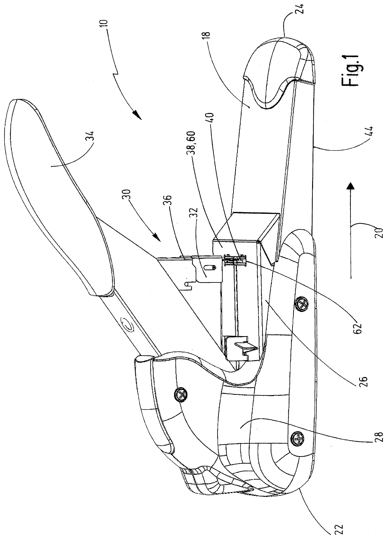
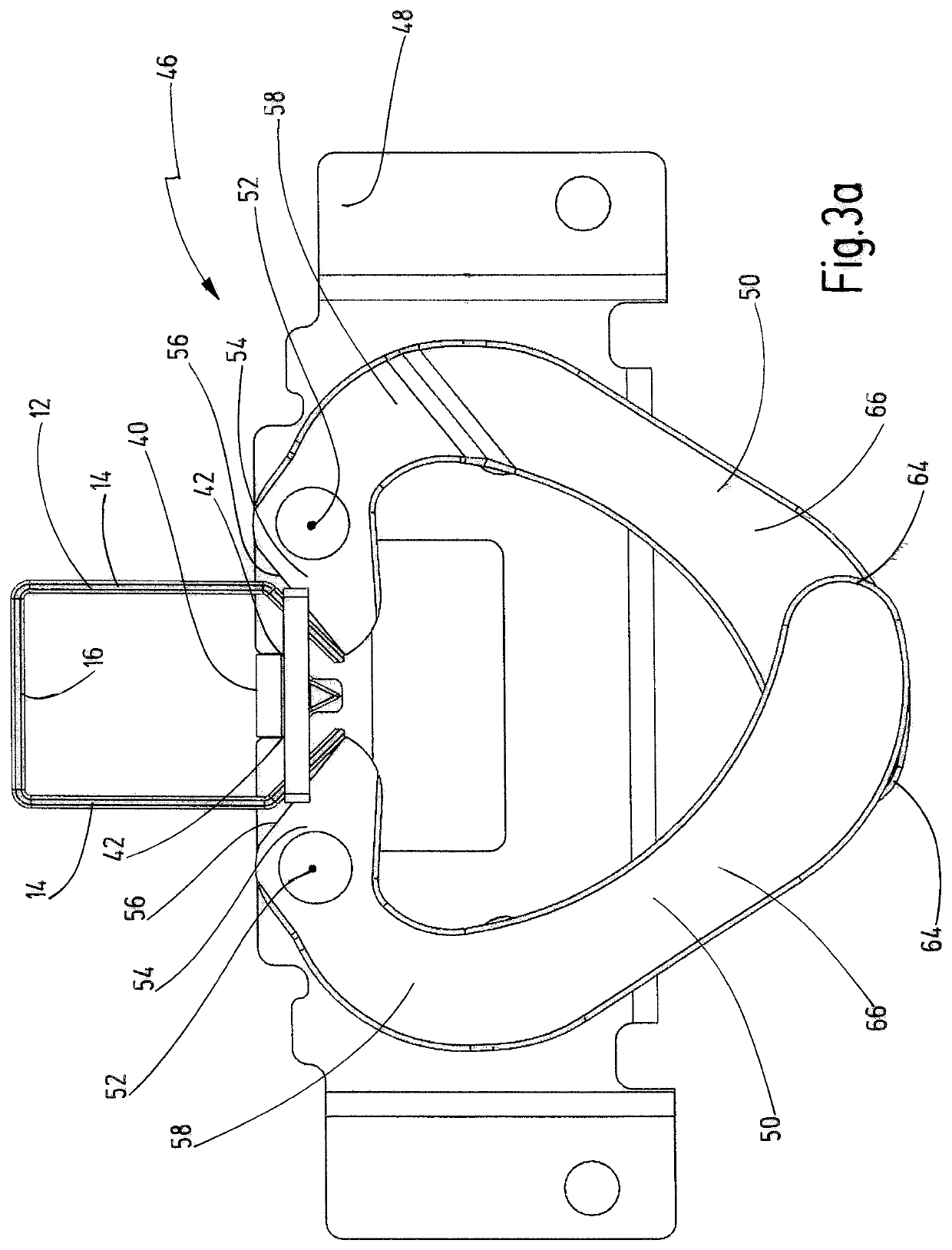
[0015]The stapler 10 illustrated in the drawing serves to staple sheet material by means of staples 12, which, as is apparent from FIG. 3a, 3b, each have two staple legs 14 and a staple crown 16 interconnecting the staple legs 14 and extending transversely to them. The staples 12 thus have the shape of a downwardly open U, wherein during the stapling operation, the staple legs 14 pierce the sheet material with their free ends and are bent over on the underside of the sheet material.

[0016]The stapler has a base part 18, which extends in a longitudinal direction 20 from a rear end 22 to a front end 24 and bears an anvil arm 26, which is mounted on the base part 18 movably towards it against a restoring force, for example of a spring. In the present exemplary embodiment, the anvil arm 26 is mounted pivotably on the base part 18 in the region of a bearing block 28 arranged close to the rear end 22. The stapler 10 also has a stapling unit 30, which has a staple magazine 32 in which the s...


PUM


Abstract

The invention relates to a stapler (10) for stapling sheet material by means of staples (12), each staple (12) having two staple legs (14) and a staple crown (16) interconnecting the staple legs (14) and extending transversely to them, with an anvil arm (26) having a support plate (38) for placing the sheet material thereon, the anvil arm (26) carrying a cutting pad (40) with two cutting edges (42) for cutting off excess end parts of the staple legs (14), with a stapling unit (30) that is pivotally mounted relative to the anvil arm (26), which stapling unit (30) comprises a staple magazine (32) receiving the staples (12) in a row with the staple crowns (16) mutually abutting and being aligned parallel to each other and a driver (36) for pushing individual staples (12) with the free ends of their staple legs (14) first through the sheet material, with a base part (18), on which the anvil arm (16) is mounted movably towards it against a restoring force, and with two two-armed bending levers (50) pivotably mounted on the anvil arm (26) about a respective pivot axis (52), each bending lever (50) having a first lever arm (54) with a bending surface (56) for bending the staple legs (14) and a second lever arm (58), wherein upon approach of the anvil arm (26) to the base part (18), the second lever arms (58) are pivoted by action of the base part (18) about the pivot axes (52) and the bending surfaces (56) bend the staple legs (14) towards each other and cut off any excess end portions by pressing against the cutting edges (42). According to the invention, it is provided that the pivot axes (52) extend substantially perpendicular to the staple crowns (16) of the staples (12) received in the staple magazine (32) and that the second lever arms (58) have end portions (66) beginning at their free ends (64) which are arranged offset to one another in the axial direction of the pivot axes (52) so that they move past one another as the anvil arm (26) approaches the base part (18).

Description

BACKGROUND[0001]The invention relates to a stapler.[0002]Such a stapler is known from EP 1 480 788 B1. The configuration thereof with an anvil arm that is movable towards a stapler base part against a restoring force and with two-armed bending levers that are pivotably mounted on the anvil arm and, when the anvil arm is pushed down, bend the staple legs that have been passed through the sheet material and cut off excess end parts of the staple legs by pressing against the cutting edges of the cutting pad makes it possible to always use the same staples for sheet material with very different total thicknesses. If only a few sheets of paper are stapled together, for the total thickness of which the staple legs are actually too long, their excess end parts are simply cut off. In order that they do not collide with one another during the bending operation, the bending levers are arranged offset to one another in a direction that extends perpendicular to the staple crowns of the staples ...

Claims


Application Information

Patent Timeline
IPC IPC(8): B25C5/02
CPCB25C5/0271
Inventor OHLSSON, ROBERT
Owner ISABERG RAPID
Why Eureka
Try Eureka