Continuous optical measuring apparatus and continous optical measuring method

a continuous optical measuring and measuring method technology, applied in the direction of instruments, biochemical apparatus and processes, fluorescence/phosphorescence, etc., can solve the problems of non-flexible material, non-flexible foundation member formed in a coil shape, and not necessarily flexible foundation member

Inactive Publication Date: 2006-11-30
UNIVERSAL BIO RESEARCH CO LTD
View PDF2 Cites 19 Cited by
  • Summary
  • Abstract
  • Description
  • Claims
  • Application Information

AI Technical Summary

Benefits of technology

[0030] Consequently, the labeling at the fixed positions can be reliably captured. In particular, if a plurality of types of labeling substances are combined to change the quantity ratio so as to perform many types of labeling, the data analysis can be made easy, or can be automized.
[0074] In the thirteenth aspect of the present invention, as described in the first aspect of the present invention, since along the moving line the light emission at the respective fixed I along the arrangement line can be measured in detail while being overlapped, precise and detailed information can be obtained for the respective fixed positions. Consequently, the labeling at the fixed positions can be reliably captured. In particular, if a plurality of types of labeling substances are combined to change the quantity ratio so as to perform many types of labeling, an effect is demonstrated where the data analysis can be made easy or can be automized. Moreover, since the rotational movement and the straight line movement can be continually performed for measurement, an effect is demonstrated where the device and the control can be simplified, and the cost can be reduced.

Problems solved by technology

That is, the foundation member is not necessarily flexible even if it is in a slender shape such as a thread, a cord, or the like, but it may be a non-flexible material such as a wire or a rod.
Moreover, it may be a non-flexible foundation member formed in a coil shape.

Method used


Image

  • Continuous optical measuring apparatus and continous optical measuring method
  • Continuous optical measuring apparatus and continous optical measuring method
  • Continuous optical measuring apparatus and continous optical measuring method

Examples


Embodiment Construction

[0089] Hereunder is a description of a continuous optical measuring apparatus and continuous optical measuring method according to an embodiment of the present invention, with reference to drawings. The description of the present embodiment should not be considered as limiting the present invention unless particularly specified.

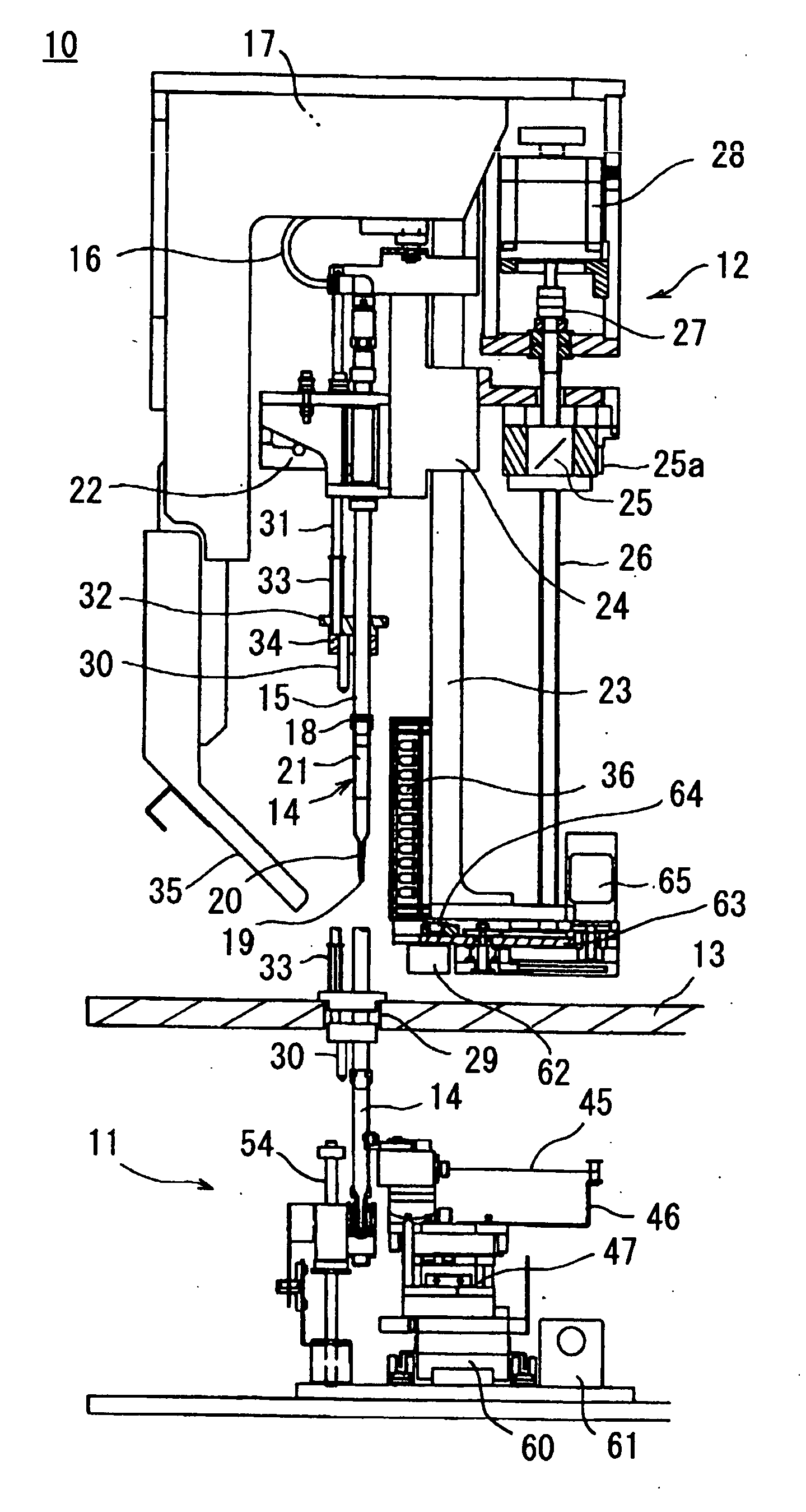
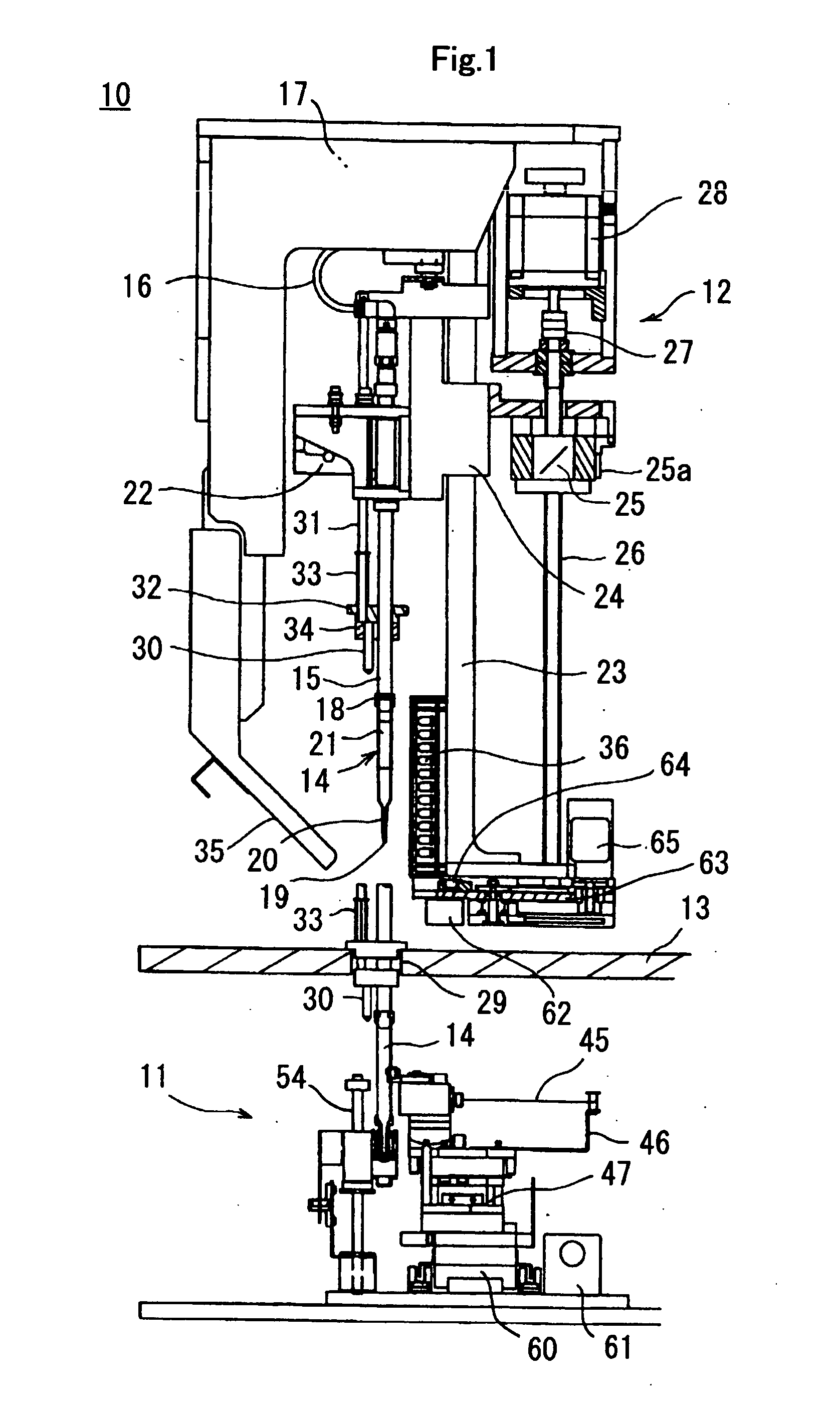
[0090]FIG. 1 is a partial cross-sectional side view of a storing, reacting and measuring apparatus 10 assembled with a continuous optical measuring apparatus 111 according to the embodiment of the present invention.

[0091] The storing, reacting and measuring apparatus 10 is an apparatus which automatically and consistently performs reaction and measurement while the abovementioned foundation member is stored in a storage part. In the storing, reacting and measuring apparatus 10, a continuous optical measuring apparatus 11 which stores the foundation member in the storage part and continually and optically measures along a line, and a storing and reacting app...


PUM

PropertyMeasurementUnit
sizeaaaaaaaaaa
lengthaaaaaaaaaa
lengthaaaaaaaaaa

Abstract

An inexpensive continuous optical measuring apparatus with high cost / performance ratio capable of obtaining the emission of light at respective fixed positions arranged on a foundation member, by a simple device or a control, and a continuous optical measuring method. The apparatus comprises: at least one transparent or semi-translucent storage part capable of storing the foundation member having a plurality of types of predetermined detection substances fixed thereto along an arrangement line at predetermined intervals, with the detection substances and their fixed positions associated; at least one light receiving part installed at a predetermined position outside of the storage part, and receiving light from the fixed positions, and receiving light from an area having a light receiving width narrower than the width of the arrangement line; and a continuous moving part which is continuously moved relatively between the light receiving part and the storage part so as to scan the fixed positions on the foundation member along a spiral moving line having the light receiving width.

Description

TECHNICAL FIELD [0001] The present invention relates to a continuous optical measuring apparatus and a continuous optical measuring method. The present invention relates to various fields requiring treatment of biopolymers or biological low molecular substances such as genes, substances of immune systems, amino acids, proteins, sugars, and the like, for example engineering fields, agricultural fields such as food processing, agricultural processing, and fishery processing, pharmaceutical fields, medical fields such as sanitation, health, immunization, diseases, and genetics, and chemical fields, and the like. [0002] In particular, the present invention relates to a continuous optical measuring apparatus and a continuous optical measuring method which are suitable for gene mutation analysis, polymorphism analysis, mapping, base sequence analysis, expression analysis, and the like. BACKGROUND ART [0003] Conventionally, there have been inventions where a DNA chip is used for determinin...

Claims


Application Information

Patent Timeline
Patent Type & Authority Applications(United States)
IPC IPC(8): G01N21/00C12Q1/68G01N21/25G01N21/64G01N35/10
CPCG01N21/6428G01N2035/1062G01N35/10G01N21/6452G01N21/64G01N21/78
Inventor TAJIMA, HIDEJI
Owner UNIVERSAL BIO RESEARCH CO LTD
Why Eureka
Try Eureka