Pressure sensor

a technology of pressure sensor and pressure gauge, which is applied in the direction of fluid pressure measurement using elastically deformable gauges, instruments, and fluid pressure measurement by mechanical elements, etc. it can solve the problems of poor welds, mechanical damage to bond wires or bonds, and unwanted open or intermittent contacts, so as to facilitate the inspection of strain gauges, facilitate the bonding and visibility of sensor contacts, and reduce problems

Active Publication Date: 2011-12-01
SENSATA TECHNOLOGIES INC
View PDF5 Cites 19 Cited by
  • Summary
  • Abstract
  • Description
  • Claims
  • Application Information

AI Technical Summary

Benefits of technology

[0013]In yet another embodiment, the electronics board further includes an oversized wire bond window adapted to provide access to sensor contacts to facilitate wire bonding and visibility of the sensor contacts. Changing the conventional rectangular shape of the wire bond window solves several problems including the formation of bubbles and voids, inspection of strain gauges and the dispensed protective gel. In a particular embodiment the oversized wire bond window includes rounded corners and is lengthened approximately on an axis along a longer dimension of strain gauges mounted on the sense element port. Such a design facilitates inspection of the strain gauges and the dispensed protective gel in the wire bond window and reduces problems due to skewing of the window with respect to the strain gauges. Additionally, it has been discovered that such an oversized wire bond shape promotes a reduction of bubbles and voids when dispensing protective gel.
[0014]In another embodiment, gel flow barriers on the electronics board include a moat to redirect gel flow. The moat includes one or more walls forming one or more trenches. The moat includes a top layer having a non-wetting surface with respect to a protective gel. By eliminating a gel dam to contain unwanted gel, there is one less separate part which needs to be attached to the electronics board. In addition to eliminating a component, the opportunity that another part catches on one gel dam is also eliminated.
[0015]A technique to form a gel flow barrier includes the steps of: fabricating a plurality of multi-layer trenches and corresponding walls in electronics printed circuit board (PCB) surrounding a board feature to be protected from a gel flow. The plurality of multi-layer walls form trenches providing a moat at least partially surrounding a board feature to be protected. Such a technique provides a cost effective mean of managing gel flow and flexibility in the placement of protection from unwanted gel flow for features on the electronic board. A technique to apply a gel includes providing a gel flow barrier on an electronics board the gel flow barrier having a non-wetting surface with respect to a protective gel, positioning the gel flow barrier to protect an electrical contact pad and providing an oversized wire bond window. The gel flow is managed by dispensing the gel into the oversized wire bond window and over wire bond pads on the electronics board such that the gel flow barrier redirects the gel thereby preventing the gel from flowing onto the electrical contact pad.
[0016]An exemplary interface connector assembly includes an upper spring guide adapted for retaining an elastic contact member and a lower spring guide adapted to attach to the upper spring guide. The elastic contact member comprises a double-ended symmetrical spring having dual tapered ends such that a contact point at each end of the spring is closer to a center axis / center line of the spring. Such an interface connector assembly provides effective spring capture without the use of expensive pogo pins or PCB's. The connector can be pre-assembled separately, and in some circumstances, the assembly can occur outside of clean-room conditions required to assemble the strain gauges and spring symmetry reduces orientation concerns during manufacturing and allows for automated feeding of the springs.
[0017]In another embodiment, the springs in the interface connector are conically tapered to further align the spring tip center towards the center of a contact receiving pad on the electronics board. A first taper effectively causes the spring to have a smaller diameter tip and therefore reduces locating concerns when aiming for a contact pad of an electronics board or ECU. Additionally, a second taper allows for reliable capture and retain of the spring in a spring guide.
[0018]Such designs and techniques described above facilitate packaging to provide high volume manufacturing and high reliability. The embodiments disclosed herein, may be employed in devices such as those manufactured by Sensata Technologies, Inc. of Attleboro, Mass., U.S.A.

Problems solved by technology

In practice, the lip is difficult to form and defects can result in poor welds due to excessive gaps between support ring and sense element port, burn through of support ring, or a laser welder missing the support ring to port interface location.
Bubbles or voids in the gel, depending on their location, sometimes allow corrosion or degradation, or cause mechanical damage to bond wires or bonds.
Presence of gel (an electrical insulator) on electrical contact spring landing pads can cause unwanted open or intermittent contacts.
The close vertical spacing of the PCB to the diaphragm can lead to a lack of gel flow in this area, leaving the glass (on which the strain gauges are mounted) unprotected from degradation (a cause of output signal offset shift).
However, there is a need to manage gel flow without use of additional components which increase costs, and in some cases require additional circuit board real estate, thereby negatively impacting space constraints.
Conventional pressure sensors typically use relatively expensive pogo pins or springs with one or two diameters.
Pogo pin solutions are expensive because they require machined housings around the springs and extra sub-assembly operations.
The solution of insert molding springs is difficult because of potentially serious difficulties with methods for properly sealing the mold against the spring, preventing mold flash, and precisely orienting the spring tips towards their target contact pads.
Conventional pressure sensors use expensive contact assemblies, seam welded components and gel dams to block the flow of protective gel from certain area on electronics boards.

Method used


Image

  • Pressure sensor
  • Pressure sensor
  • Pressure sensor

Examples


Embodiment Construction

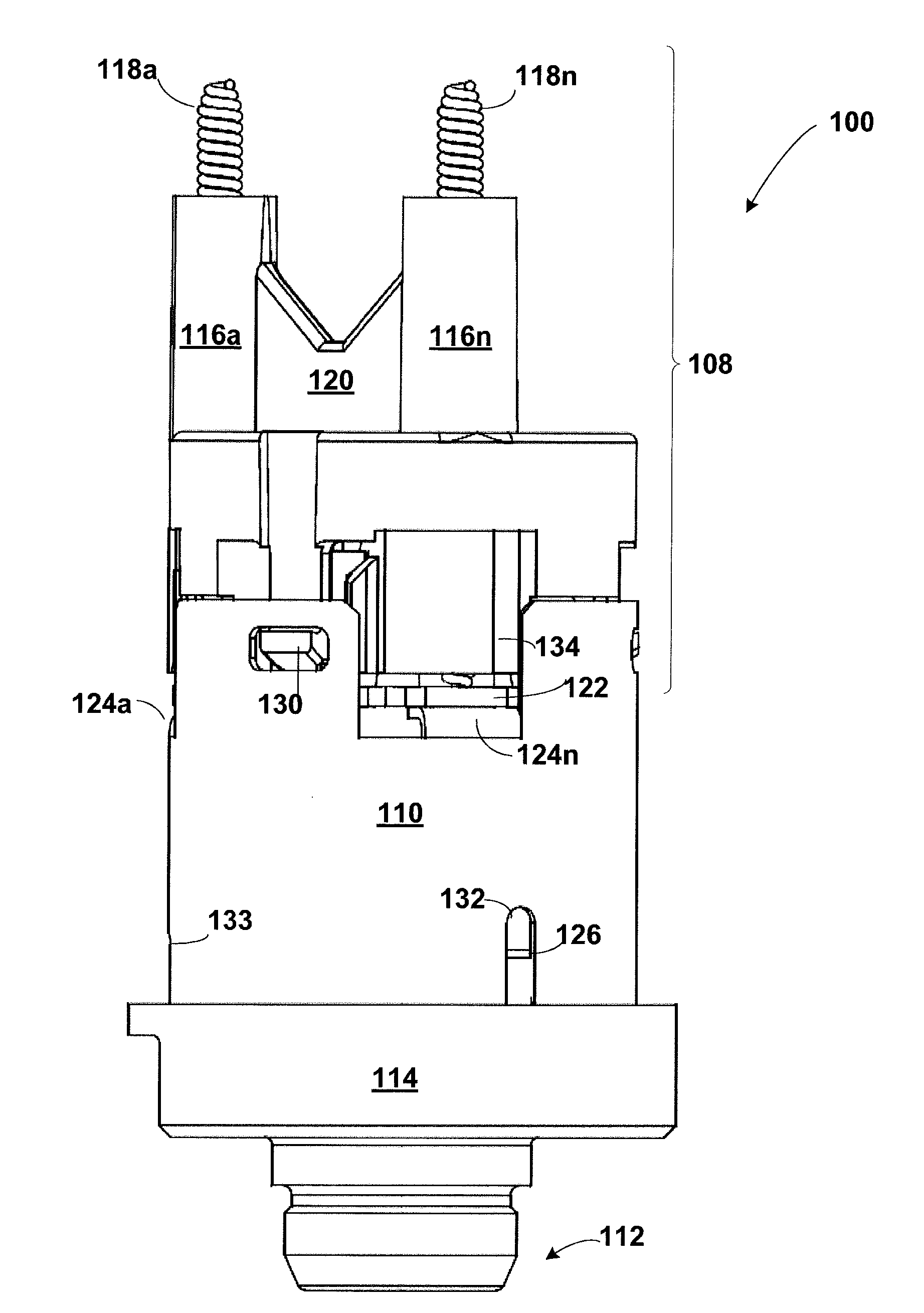
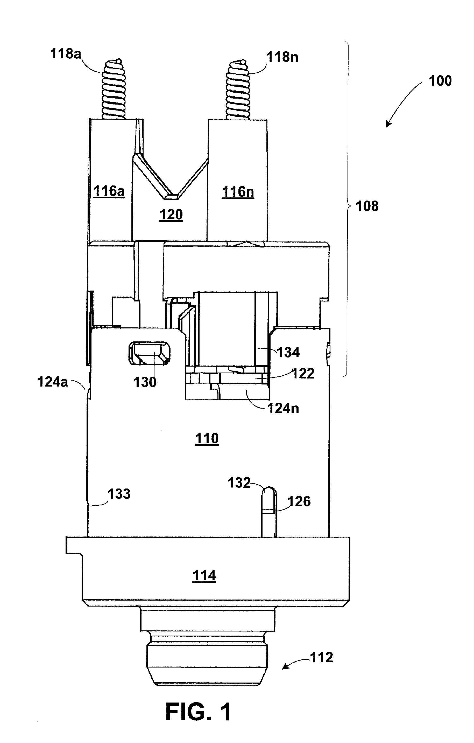
[0030]Embodiments of the invention disclosed herein provide for a novel pressure sensor for use in measuring pressure. Embodiments disclosed herein include a newly designed gel flow barrier that isolates certain printed circuit board (PCB) features and components from protective gel applied to other areas of the PCB. Additionally, embodiments include a newly designed contact spring adapted to facilitate manufacture of the pressure sensor while minimizing the effect of tolerance stack-up. In particular, in one embodiment, a support ring includes planar mounting tabs which provide stable support for a single electronics board and support for elastic contact members, for example, double-ended symmetrical springs having a conical taper at both ends.

[0031]FIG. 1 illustrates a pressure sensor 100 configured in accordance with one example embodiment. The pressure sensor 100 includes a contact housing sub-assembly 108 which includes an upper spring guide 120 (also referred to as upper conta...


PUM

PropertyMeasurementUnit
volumeaaaaaaaaaa
flexibleaaaaaaaaaa
mechanical stressesaaaaaaaaaa

Abstract

A pressure sensor includes a sense element port, a support ring and a plurality of interference fit slits to provide a flexible interference fit between the sense element port and the support ring to form a substantially flush lap joint. The sensor also includes an electronics board inside the support ring and attached to planar mounting tabs which provide a stable mounting. Gel flow barriers protect electronics board features from unwanted non-conductive gel. Double-ended symmetrical, tapered contact springs provide manufacturing cost savings and contribute to improved alignment of an interface connector of the sensor.

Description

FIELD OF THE INVENTION[0001]This invention relates generally to pressure sensors and more particularly to sensors using strain gauge technology for sensing pressure change to produce an electrical signal related to such change and employing electronics for processing and amplifying the signal.BACKGROUND OF THE INVENTION[0002]Although the use of strain gauge technology for converting changes in fluid pressure to related electrical signals is known, there exists a need to provide sensors which are more easily manufactured and which have improved reliability and optimum life expectancy. There is also a need to minimize the cost of producing the sensors so as to make it more economically feasible to use them in given applications and thus increase manufacturing volume with resulting savings in large volume manufacturing techniques.[0003]In issued U.S. Pat. No. 6,763,724, assigned to the assignee of the present invention, a pressure sensor using strain gauge technology is disclosed and c...

Claims


Application Information

Patent Timeline
Patent Type & Authority Applications(United States)
IPC IPC(8): G01L9/04
CPCG01L19/0627G01L19/0084
Inventor WILLNER, ANDREW F.TOMASSO, LOUISFRAONE, GIOVANNIAMBADY, PRASANTH
Owner SENSATA TECHNOLOGIES INC
Why Eureka
Try Eureka