Quick change device for the oscillating tool of a vibration welding machine

Inactive Publication Date: 2007-04-19
BRANSON ULTRASCHALL NIEDERLASSUNG DER EMERSON TECH
View PDF4 Cites 7 Cited by
  • Summary
  • Abstract
  • Description
  • Claims
  • Application Information

AI Technical Summary

Benefits of technology

[0006] An object of the present invention is to create a quick change device for an oscillating tool of a vibratory unit of a vibration welding machine for receiving a work-piece half to be welded, which allows to clamp and release the tool and thus to exchange the tool as quickly as possible.
[0009] In the simplest case, the screws are operated manually (using a torque wrench). In an automatic embodiment, one or more screwdrivers are provided and integrated into the vibration welding machine for actuating the screws. In each case, only a limited number of screws are required due to the use of the clamp bodies so that the changing of the oscillating tool can be performed relatively quickly and easily.

Problems solved by technology

While there are fast and simple change devices for the stationary tool (bottom tool), the change of the oscillating tool usually requires the release of many screw connections.
The release of these many screw connections requires a great amount of time.
However, the underlying problem still remained: mechanical release of screw connections and their defined tightening.
Although there have already been attempts at accelerating the changing of the oscillating tool through automation, these attempts have not yet proven useful in practice.

Method used


Image

  • Quick change device for the oscillating tool of a vibration welding machine
  • Quick change device for the oscillating tool of a vibration welding machine
  • Quick change device for the oscillating tool of a vibration welding machine

Examples


Embodiment Construction

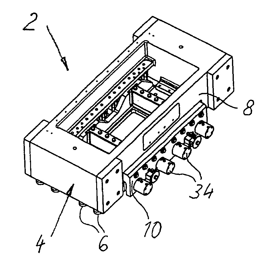
[0019] The drawings show an oscillating head 2 of a vibration welding machine (not described in greater detail), wherein the coils of the oscillating head have been omitted in order to simplify the drawing. Since the non-describe part of the vibration welding machine with machine frame, lift table, stationary tool (bottom tool) for receiving the stationary work-piece half, etc. can have a conventional design, it is not described in greater detail here.

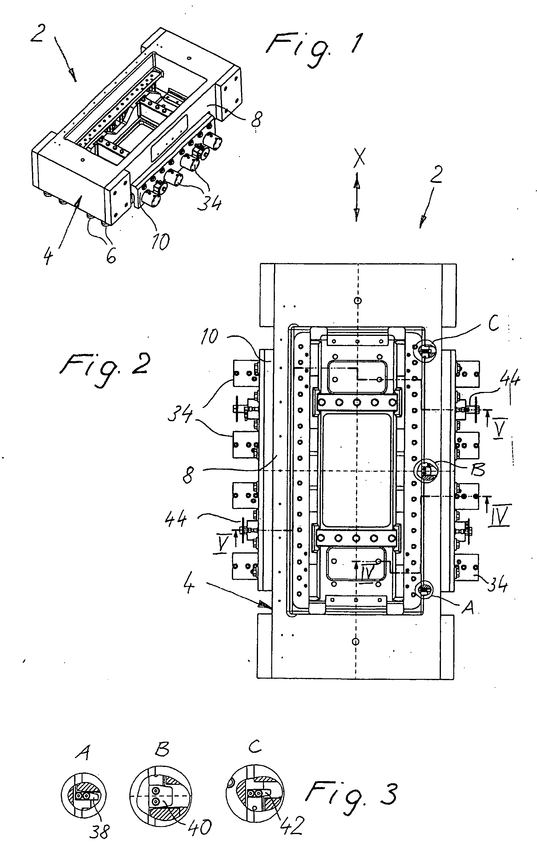
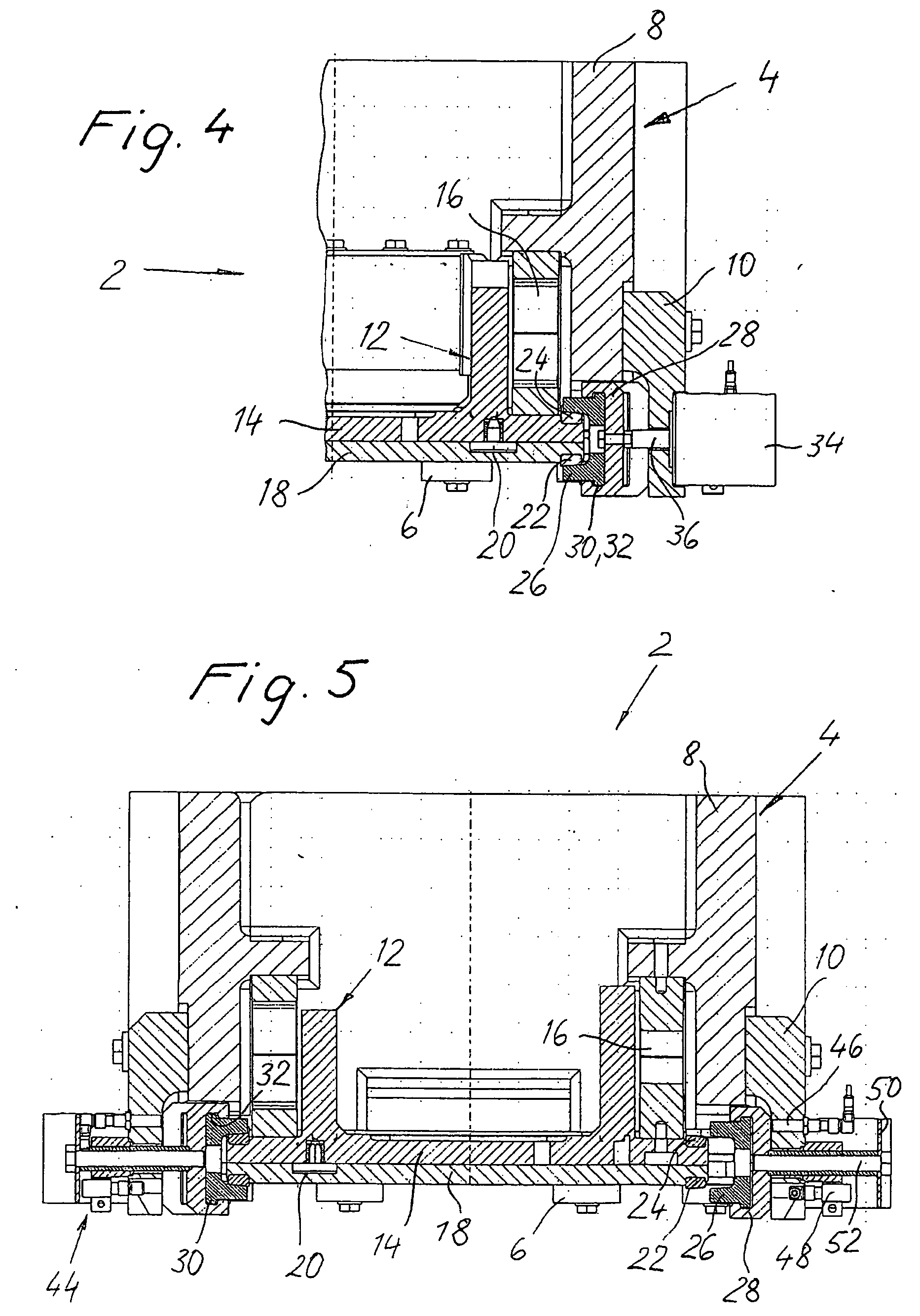
[0020] The vibration head 2 has a stationary section in the shape of a bridge 4, which is mounted on the machine frame (not shown) via dampers 6. The bridge 4 is made up of a substantially rectangular frame part 8, to both sides of which are attached longitudinally running, bar-shaped frame parts 10.

[0021] The vibration head 2 comprises an oscillating section in the form of a vibratory unit 12, which includes a vibratory plate 14. The vibratory unit 12 and thus the vibratory plate 14 are suspended from the bridge 4 via leaf springs 1...


PUM

PropertyMeasurementUnit
Forceaaaaaaaaaa
Angleaaaaaaaaaa
Lengthaaaaaaaaaa

Abstract

A quick change device for an oscillating tool that can be attached to the vibratory unit of a vibration welding machine. The quick change device comprises several clamp bodies, through which a vibratory plate of the vibratory unit and a tool plate of the tool are connected with each other in a force-fit manner. The clamp bodies are mounted in a movable manner on the machine frame or on the vibratory unit in order to be able to be displaced between clamping and opening positions for closing or opening the force-fit connection. According to a preferred embodiment, the actuating devices are made up of screws, which serve to both tighten and release the clamp bodies as well as to ensure the force-fit connection.

Description

BACKGROUND OF THE INVENTION [0001] The present invention relates to a quick change device for the tool that can be attached to the vibratory unit of a vibration welding machine for receiving a work-piece half to be welded. [0002] A vibration welding machine has an oscillating tool (upper tool) and a stationary counter piece (bottom tool) for the positive holding of the work-piece halves (plastic parts) to be welded. The change of the work pieces in production (e.g. in the case of a dashboard from left- to right-hand drive) usually also requires the change of the tools, which needs to take place quickly to save time. [0003] While there are fast and simple change devices for the stationary tool (bottom tool), the change of the oscillating tool usually requires the release of many screw connections. Due to the great dynamic forces affecting the vibratory unit (typical acceleration values during the welding process are 50 to 300 g), the oscillating tool is connected in a force-fit manne...

Claims


Application Information

Patent Timeline
IPC IPC(8): B23K1/06
CPCB23K20/1205B29C65/7841B29C66/54B29C66/8167B29C65/0618B29C66/841B29C65/08B23K37/047B29C66/80B29C66/81264
Inventor JUNKER, NORBERTLOTZ, WILFRIED
Owner BRANSON ULTRASCHALL NIEDERLASSUNG DER EMERSON TECH
Why Eureka
Try Eureka