Camshaft adjusting device

a technology of camshaft and adjusting device, which is applied in the direction of machines/engines, mechanical equipment, engine components, etc., to achieve the effect of cost-effectiveness and functional reliability

Active Publication Date: 2017-03-30
SCHAEFFLER TECH AG & CO KG
View PDF1 Cites 1 Cited by
  • Summary
  • Abstract
  • Description
  • Claims
  • Application Information

AI Technical Summary

Benefits of technology

The present invention provides a camshaft adjuster that allows for reliable and cost-effective center locking of the rotor. The adjuster includes a recess in a locking slot on the stator that allows the valve pin in the center locking position to move into the recess. This recess is particularly useful during start-up of the internal combustion engine when the additional switching position is only needed for a limited time. The end section of the valve pin is tapered to reduce friction when moving into the center locking position. The tapering makes it easier to move the valve pin out of the recess during adjusting movement between the rotor and stator. The valve pin acts as the first valve function pin and can be controlled by the pressure medium level in the locking slot to switch the bridging line between two working chambers. This allows for precise control of the camshaft adjustment without the need for additional components.

Problems solved by technology

In this state, the locking pins have not yet been completely forced out of the locking slot, as a result of which at least one locking pin may jam on the locking slot as a result of the applied torque.

Method used


Image

  • Camshaft adjusting device
  • Camshaft adjusting device
  • Camshaft adjusting device

Examples


first specific embodiment

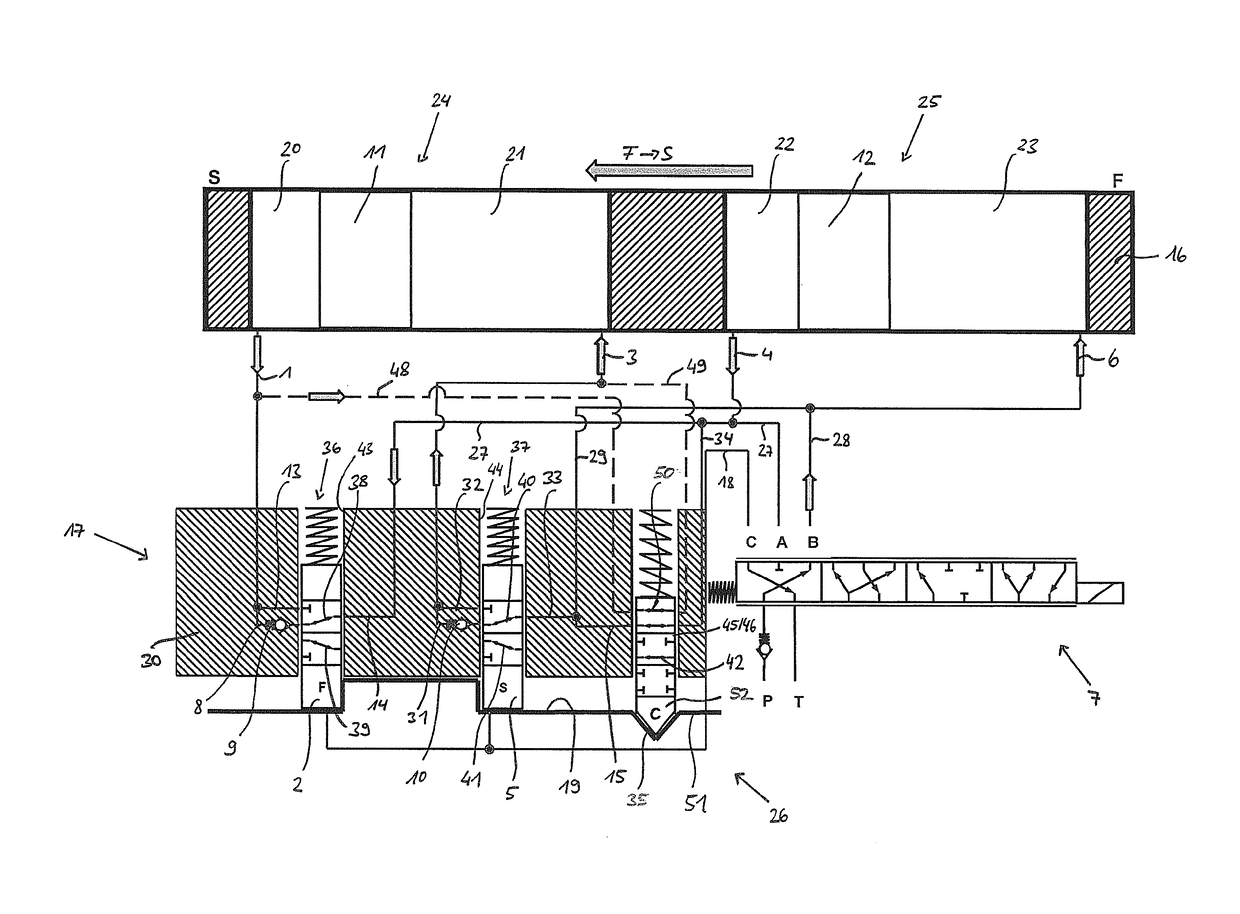
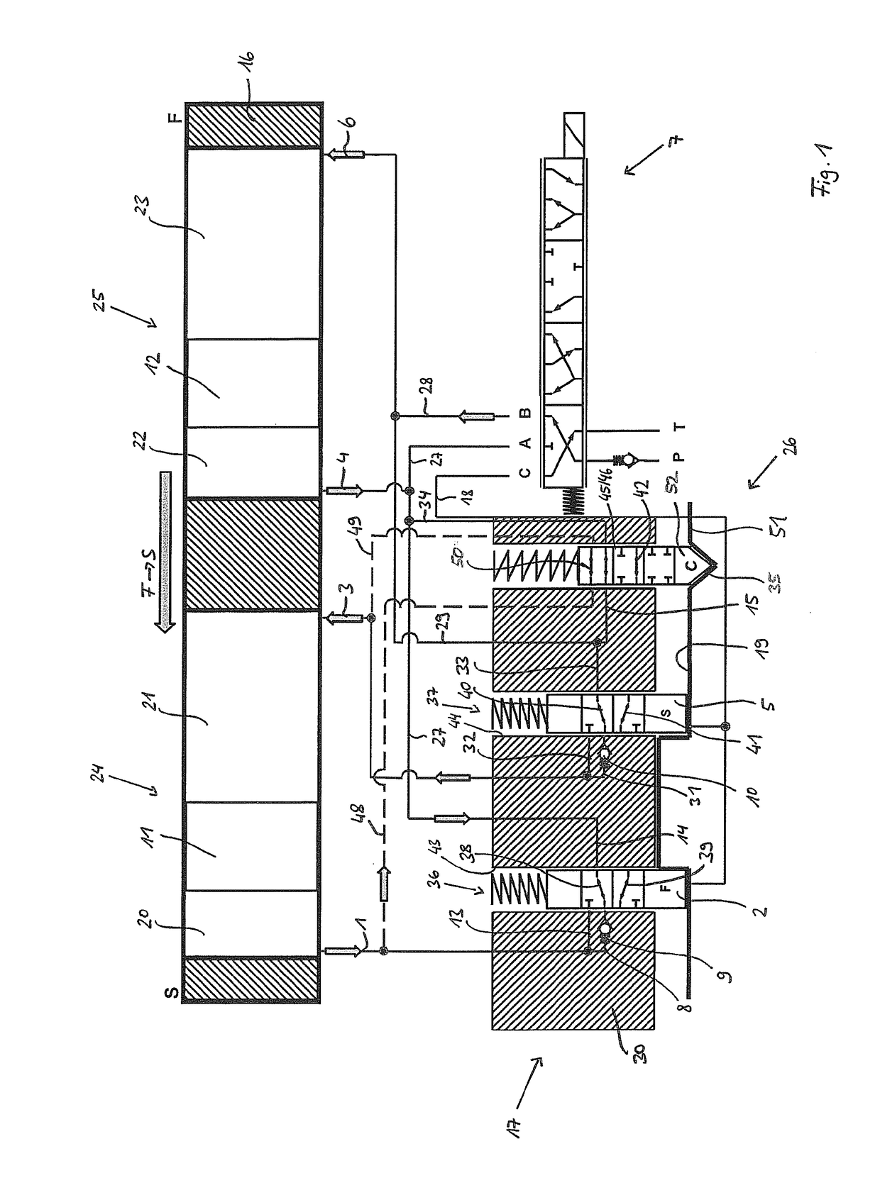
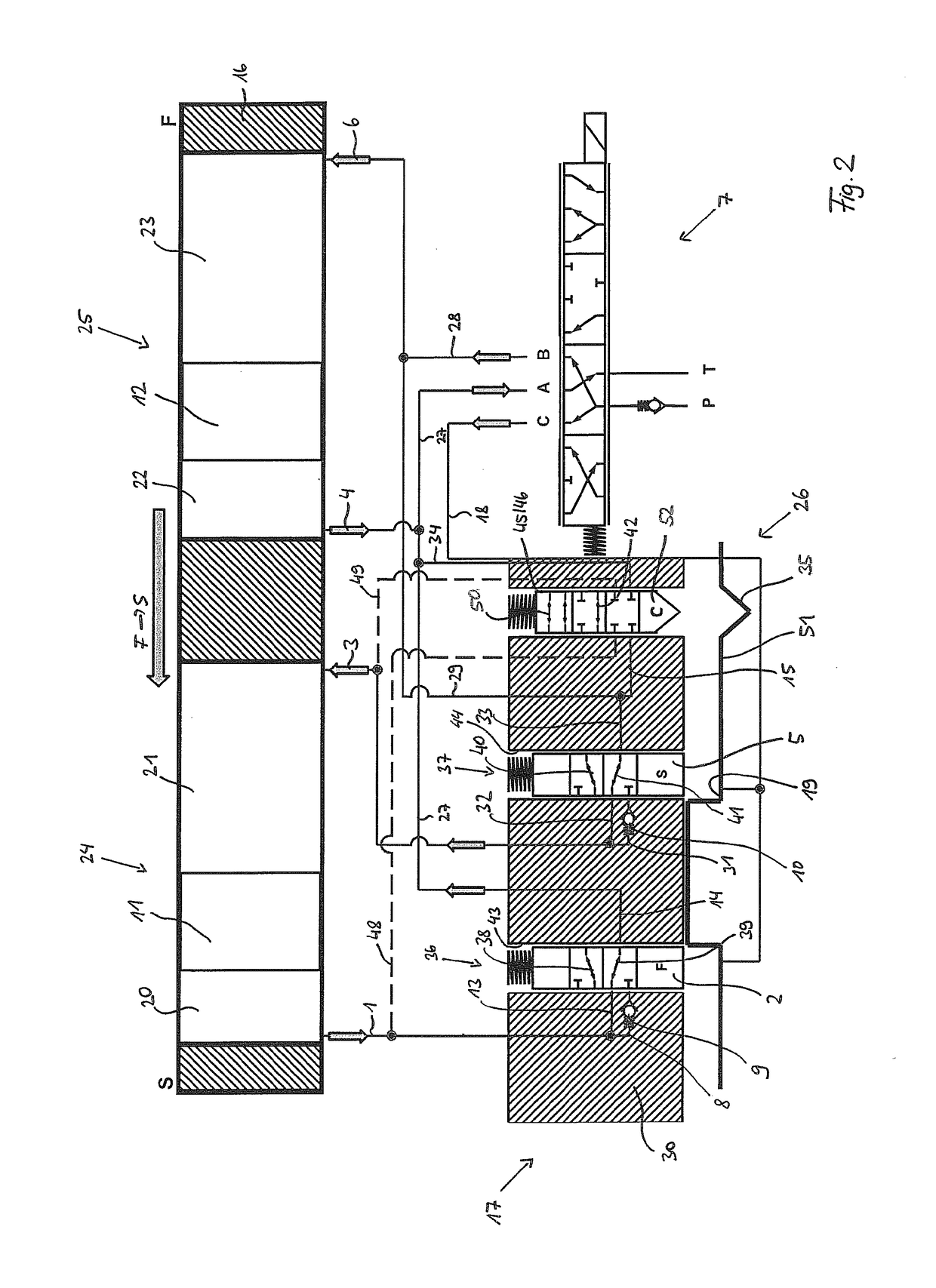
[0026]FIGS. 1 and 2 show the present invention, whereas a second alternative specific embodiment is shown in FIG. 3, the first specific embodiment being preferably used in practice.

[0027]In FIGS. 1 through 3, it is apparent that, according to the solution according to the present invention, a check valve 9 and 10, respectively, is situated in a rotor hub 30 of rotor 17 in spatial proximity to locking pins 2 and 5. Locking pin 2 is fluidically connected via pressure medium line 14 to pressure medium line 27. In addition, pressure medium line 1 is fluidically connected via pressure medium lines 8 and 13 to an accommodating space 43 of locking pin 2. Pressure medium lines 8 and 13 are fluidically connected in parallel. Pressure medium line 8 and 13 are fluidically connected to second pressure medium line 14 as a function of the switching position of a first valve device 36. Thus, the first valve device 36 is formed by accommodating space 43 and locking pin 2 guided therein. In a first ...


PUM


Abstract

A camshaft adjusting device including—a vane cell adjuster and—a central locking device (26) for locking the rotor (17) with respect to the stator (16), wherein—at least one first valve functional pin (46) is provided in the rotor hub (30), and the working chambers (20, 21, 22, 23) with different directions of action can be fluidically connected to one another via said valve functional pin,—in a first switch position, the first valve functional pin (46) fluidically connects at least two first working chambers (20, 21) with different directions of action to each other via a non-return valve (9, 10) during a movement from the direction “early” or “late” into the central locking position,—in a second switch position, the first valve function pin (46) fluidically separates the at least two first working chambers (20, 21) with different directions of action,—a bridging line (50) is provided for a fluid-free connection of the two first working chambers (20, 21), and—the bridging line (50) can be switched by a valve pin (45).

Description

[0001]The present invention relates to a camshaft adjusting device having. [0002]Camshaft adjusting devices are generally used in valve trains of internal combustion engines in order to alter the valve opening and closing times, as a result of which the consumption values of the internal combustion engine and the operating behavior may generally be improved.BACKGROUND[0003]One specific embodiment of the camshaft adjusting device proven in practice includes a vane cell adjuster with a stator and a rotor, which delimit an annular space, which is subdivided by projections and vanes into multiple working chambers. The working chambers may be selectively acted upon by a pressure medium, which is fed in a pressure medium circuit via a pressure medium pump from a pressure medium reservoir into the working chambers on one side of the vanes of the rotor and is fed from the working chambers on the respective other side of the vanes back to the pressure medium reservoir. The working chambers, ...

Claims


Application Information

Patent Timeline
Patent Type & Authority Applications(United States)
IPC IPC(8): F01L1/344
CPCF01L1/3442F01L2001/34426F01L2001/34463F01L2001/34466
Inventor ZSCHIESCHANG, TORSTEN
Owner SCHAEFFLER TECH AG & CO KG
Why Eureka
Try Eureka