Wind energy plant having a twistable nacelle cable guide

a technology of wind energy plant and nacelle, which is applied in the direction of cable termination, machines/engines, mechanical equipment, etc., can solve the problems of high wear in this area, specifically twisting and shortening, and the area is subject to a double load, so as to minimize the risk of excessive heating, maximize the twisting effect, and advantageous field line profile

Active Publication Date: 2012-01-12
REPOWER SYST AG
View PDF2 Cites 17 Cited by
  • Summary
  • Abstract
  • Description
  • Claims
  • Application Information

AI Technical Summary

Benefits of technology

[0023]In the simplest case, two guide rings are sufficient, one at the top and one at the bottom. However, it is also possible to provide one or more further guide rings (intermediate rings) which are arranged in between. This offers the advantage that, even in the case of relatively long cables and large cable diameters, it is possible to maintain the desired helical position. In general, the additional guide rings are arranged loosely, in order that they can also rotate to a different extent, depending on their positioning, between the upper and lower guide rings.
[0024]In order to achieve maximum twisting, it is advantageous for the individual cables to be arranged at approximately equal intervals on the envelope surface of the guide rings. The separation minimizes the risk of excessive heating resulting from the current-carrying cables being concentrated. Individual positions may remain free in order in this way to provide space for accommodation of components for attachment or bearing of the guide rings. The cables are advantageously arranged on the inner and outer envelope surfaces. This allows a space-saving arrangement with the cables, and therefore the use of guide rings with a smaller diameter. It may be expedient to provide the same angle separation for the arrangement of the cables on the inner and outer envelope surfaces. This allows cable pairs to be formed, for example from two arranged on the outside and one on the inside, which have a particularly advantageous field line profile.
[0025]The guide ring expediently has a circumference which is greater than the added thickness of the cables arranged along the circumference, to be precise by a factor of 1.7 to 2.2. It has been found that this circumferential size results in an optimum ratio of the space required and an adequate separation between the individual cables in the event of severe twisting.
[0026]According to one preferred embodiment, which may require separate protection, flexible strain relief is provided on the nacelle for the cables which are hanging into the tower. This is advantageously in the form of a mesh which surrounds the cable and has a suspension device at its upper end. This allows the cables to be suspended on the nacelle in a manner which is functionally reliable and robust even in the event of severe twisting, as well. The mesh allows flexibility for angle deflections such as those which occur during twisting and in the process also tolerates twisting of the cable section within the mesh. Furthermore, the mesh offers the advantage that it tightens when subjected to heavy load, thus providing a self-securing effect. It is also particularly suitable for large and heavy cables.
[0027]It has been found to be particularly advantageous for the cables also to be continued separated when routed further in the nacelle. In particular, it is preferable for the cables to be arranged by means of metallic supports such that they are combined on the basis of phase systems, and the respective phase systems are guided separately by metallic supports, in order to avoid inductive heating of the support. An arrangement such as this increases the current load capacity of the cables, because of the reduced heating of the cables. For example, the cable reduction factor may be increased from about 0.55 to about 0.75, while continuation of the cable run in the area of the nacelle in a harness leads to an increase in the reduction factor by about 10% (see also DIN VDE 0298—Part 4). The higher current load capacity of the cables allows the choice and number of the cables in this area to be optimized for the load level and / or costs.
[0028]According to one preferred embodiment, signal cables with a small diameter may, however, be guided freely suspended in a harness in the interior of the guide rings. This has the advantage that, when the tower is caused to oscillate, the signal cables cannot carry out such severe oscillations because of the limiting by the guide ring, and are therefore less severely mechanically loaded.

Problems solved by technology

This area is therefore subject to a double load, specifically twisting and shortening.
The wear in this area is therefore high.

Method used


Image

  • Wind energy plant having a twistable nacelle cable guide
  • Wind energy plant having a twistable nacelle cable guide
  • Wind energy plant having a twistable nacelle cable guide

Examples


Embodiment Construction

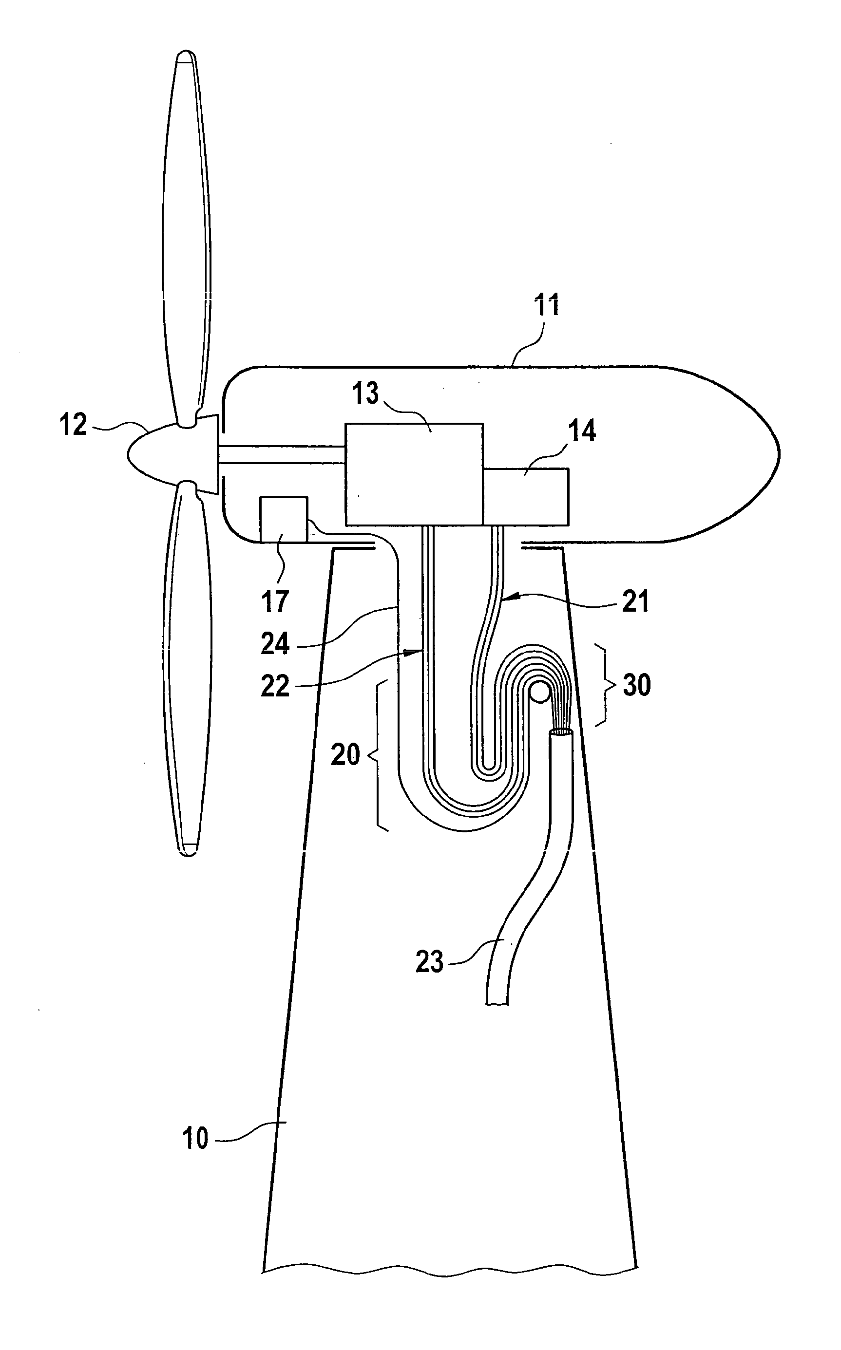
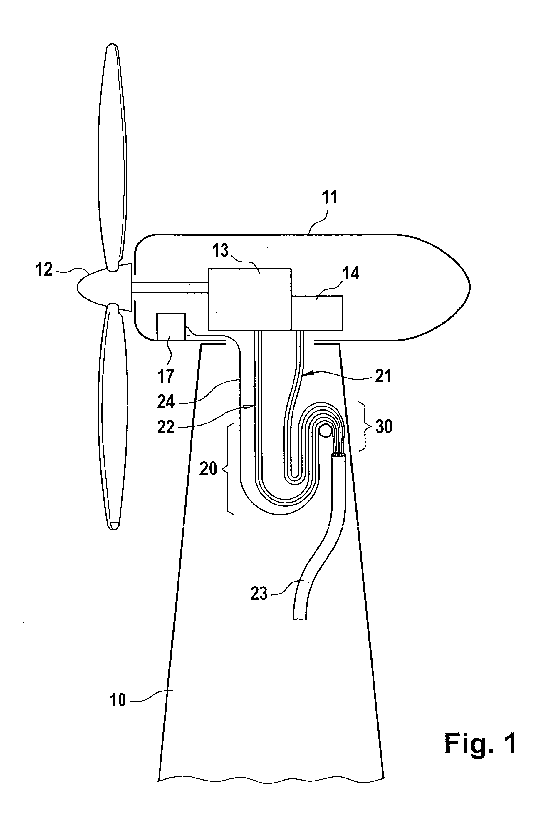
[0038]One exemplary embodiment of a wind energy installation according to the invention comprises a tower 10 with a nacelle 11 at its upper end. This is arranged such that it can swivel in the azimuth direction, by means of a motor or bearing, and has a rotatable wind rotor 12 on its end face. Via a drive shaft (not illustrated), it drives a generator 13, which is arranged in the nacelle and has a converter 14, converting the mechanical drive power of the wind rotor 12 to electrical power. In order to output the electrical power that is produced, a cable is arranged in the tower 10, comprising a plurality of cables 21, 22 for connection to the stator or rotor of the generator 13 (and possibly further signal cables 24 to an operating control system 17 for the wind energy installation), and a section 23, which hangs downward in the tower 10. The cables 21, 22 are guided from the nacelle 11 into the tower 10 by means of a loop 20 and an opposing loop 30.

[0039]Reference will now be made...


PUM


Abstract

A wind energy installation includes a tower and a nacelle arranged at the top of the tower such that it can swivel in the azimuth direction. The installation also includes a plurality of cables which are guided via a loop from the tower into the nacelle, the cables being held at a distance from one another in the loop by means of rotationally fixed and loose holders. The holders each have receptacles for attachment of the cables with a predetermined circumferential separation. The holders include a lower rotationally fixed guide ring and an aligning upper loose guide ring. A loop guide is formed such that the loop is subdivided by means of the rotationally fixed lower guide ring into a curved untwisted area and an extended twisted area.

Description

REFERENCE TO RELATED APPLICATIONS[0001]This application is a national stage application under 35 USC 371 of International Application No. PCT / EP2010 / 001789, filed Mar. 22, 2010, which claims the priority of German Patent Application No. 10 2009 013 728.9, filed Mar. 20, 2009, the contents of which prior applications are incorporated herein by reference.FIELD OF THE INVENTION[0002]The invention relates to a wind energy installation having a tower and a nacelle which is arranged at the top on the tower such that it can swivel. A plurality of cables lead from there into the tower, to be precise in the form of a loop. The cables allow the nacelle to swivel in the azimuth direction, by twisting.BACKGROUND OF THE INVENTION[0003]In the case of modern types of wind energy installations with a horizontal rotor axis, alignment with the wind is necessary. This is done by swiveling the nacelle with respect to the fixed tower in the azimuth direction, in order in this way to slave it to the main...

Claims


Application Information

Patent Timeline
Patent Type & Authority Applications(United States)
IPC IPC(8): H02G3/00
CPCF03D11/00F03D11/0066Y02E10/726Y02E10/722H02G11/003F03D80/00F03D80/85F03D80/70Y02E10/72
Inventor SCHUBERT, MATTHIAS
Owner REPOWER SYST AG
Why Eureka
Try Eureka