
Reverse tuck lock

a reverse tucking and lock technology, applied in the field of folding containers, can solve the problems of affecting the folding process, affecting the storage and/or shipping of large quantities of items, and not always readily available tapes and adhesives, etc., and achieve the effect of convenient storage and/or shipping a large quantity of items

Active Publication Date: 2017-04-06
INNOVATIVE DESIGN CONCEPTS
View PDF5 Cites 5 Cited by
  • Summary
  • Abstract
  • Description
  • Claims
  • Application Information

AI Technical Summary

Benefits of technology

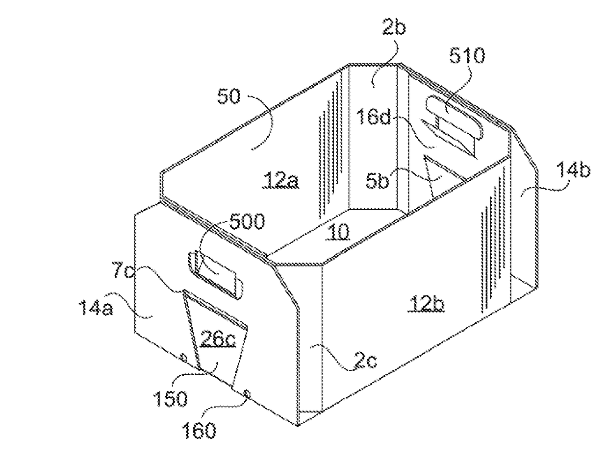
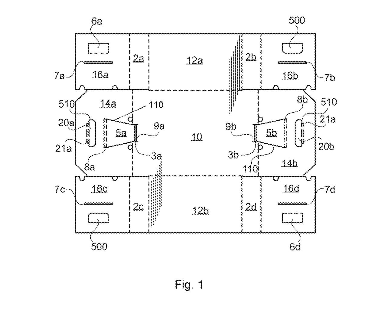
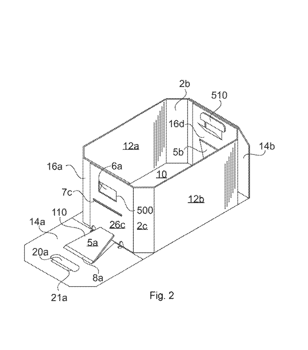
The present invention is a foldable container that can be moved from a flat to three-dimensional configuration. The containers have structural features that allow them to be stacked on top of each other, making it easy to store and ship items. The containers also have a reverse tuck lock feature that securely holds them in the three-dimensional configuration without requiring tape or adhesion. The key feature is a tab member that can be moved between locked and unlocked configurations. The container can be easily moved from the three-dimensional to flat configuration and back again without affecting its structural integrity.

Problems solved by technology

This often results in the containers being assembled by personnel that may or may not be familiar with the process of folding a particular container.
Unfortunately, such tapes and adhesives are not always readily available.
Furthermore, tapes and adhesives can damage containers, can complicate folding procedures, can limit how the container is used, and can hinder or prevent containers from later being moved back to their flat configurations for storage and / or shipping of the containers.
Some containers are subject to environmental conditions and / or damaging substances.
When fully packed, each direct-contact ice-pack container is relatively heavy.
These containers are then stacked on top of each other in a refrigerated truck and shipped across the country, likely experiencing jostling and impact loads along the way.
These pools of fluid can create potential hazards associated with potential contamination of the chicken and / or reduced structural integrity of the container.
Additional potential hazards are associated with the fluid refreezing within the container.
Unfortunately, the addition of a drain hole can decrease the structural strength of the panel.
Unfortunately, this top-locking feature decreases the bearing surface at the top of the end panels.
Furthermore, the top-locking feature is ineffective if it is not completely engaged, often causing product or other items, such as chicken and / or ice, to spill out of the container.
Furthermore still, even if the top-locking feature is completely engaged, it is subject to becoming disengaged during filling, handling, loading, shipping, and / or unloading.
Furthermore yet, it is often difficult or impossible to inspect the top-locking feature to determine whether the locking feature is disengaged and / or is likely to become disengaged.
Various containers of the prior art have been developed to solve various problems and to serve various needs, but each has its limitations and drawbacks.
Other limitations of the locking features of the prior art include limited strength capabilities.
For instance, many such locking features include one or more feature that weakens the locking feature such that the locking feature is likely to break well before the material of the container has reached its loading capability.
In other instances, however, especially when tape and / or other adhesives are not allowed or are otherwise undesirable, the locking feature is simply allowed to remain as a weak-point of the container.
To the extent that some foldable containers can be fabricated from stiffer materials, such as plastic, there are few options, many of which are not feasible for use with both flexible material and stiffer material.

Method used


Image

  • Reverse tuck lock
  • Reverse tuck lock
  • Reverse tuck lock

Examples


Embodiment Construction

[0079]As required, a detailed embodiment of the present invention is disclosed herein; however, it is to be understood that the disclosed embodiment is merely exemplary of the principles of the invention, which may be embodied in various forms. Therefore, specific structural and functional details disclosed herein are not to be interpreted as limiting, but merely as a basis for the claims and as a representative basis for teaching one skilled in the art to variously employ the present invention in virtually any appropriately detailed structure.

[0080]Referring to FIG. 1, a preferred embodiment of a flat pattern of the present invention includes a bottom panel 10, side panels 12a, 12b extending outward from opposed sides of the bottom panel 10, and end panels 14a, 14b extending outward from opposed ends of the bottom panel 10. In some embodiments, the side panels extend substantially between each end of the bottom panel and the end panels extend substantially between each side of the ...


PUM


Abstract

A foldable container moveable between a flat configuration and a three-dimensional configuration is provided. The container includes a first panel having a first engagement feature, a second panel having a second engagement feature, and a third panel having a third engagement feature. The first engagement feature is configured to engage with the second engagement feature so as to secure the container in the three-dimensional configuration. The first engagement feature is also configured to engage with the third engagement feature so as to inhibit the first engagement feature from becoming disengaged from the second engagement feature.

Description

CROSS REFERENCES[0001]This application is a continuation application of co-pending U.S. patent application Ser. No. 14 / 947,469, filed Nov. 20, 2015, which claims priority pursuant to 35 U.S.C. 119(e) to U.S. Provisional Patent Application Ser. No. 62 / 236,419, titled “Foldable Container”, filed Oct. 2, 2015, the entire disclosures of which are incorporated herein by reference. Furthermore, this application claims directly the benefit of, and priority based upon, co-pending U.S. Provisional Patent Application Ser. No. 62 / 236,419, titled “Foldable Container”, filed Oct. 2, 2015, the entire disclosure of which is herein incorporated by reference.FIELD OF THE INVENTION[0002]The present invention relates generally to foldable containers. More specifically, the present invention is concerned with a locking feature for securing foldable containers in a three-dimensional configuration.BACKGROUND OF THE INVENTION[0003]Foldable containers are commonly used to store and / or ship various products...

Claims


Application Information

Patent Timeline
Patent Type & Authority Applications(United States)
IPC IPC(8): B65D5/30B31B1/60B65D5/468B65D5/20B65D5/42
CPCB65D5/307B65D5/2038B65D5/4266B31B2203/084B31B1/60B31B2201/6095B65D5/4608B65D5/0015B65D5/106B65D5/308B65D81/26B31B50/734B31B50/60B31B2100/0024
Inventor WILEY, TED E.
Owner INNOVATIVE DESIGN CONCEPTS
Learn More