Eureka AIR delivers breakthrough ideas for toughest innovation challenges, trusted by R&D personnel around the world.

Stator fixing structure

Active Publication Date: 2017-04-06
ASIA VITAL COMPONENTS SHENZHEN CO LTD
View PDF1 Cites 1 Cited by
  • Summary
  • Abstract
  • Description
  • Claims
  • Application Information

AI Technical Summary

Benefits of technology

The present invention provides a stator fixing structure that includes a fixing member and a tube. The stator and fixing member are fitted around the tube in a bottom-up sequence to ensure a tight fit without sliding. The fixing member has a main body with a contact surface and an engaging unit that presses against the outer surface of the tube to form a tight connection. This results in improved efficiency and a more secure stator fitting which can be easily connected to other components without the need for glue.

Problems solved by technology

However, using glue to connect the stator to tube or the base has the following disadvantages: (1) additional labor time is required in the whole manufacturing process, causing higher manufacturing costs, and it is apt to glue-overflowing; (2) when one component, such as the stator, is broken, the whole structure is needed to be substituted, causing wasting much resources; and (3) the stator is heated in operation and apt to slide when being connected by gluing.

Method used


Image

  • Stator fixing structure
  • Stator fixing structure
  • Stator fixing structure

Examples


Embodiment Construction

[0026]The present invention will now be described with a preferred embodiment thereof and by referring to the accompanying drawings. For the purpose of easy to understand, elements that are the same in the preferred embodiments are denoted by the same reference numerals.

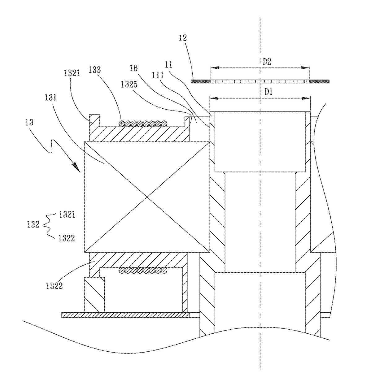
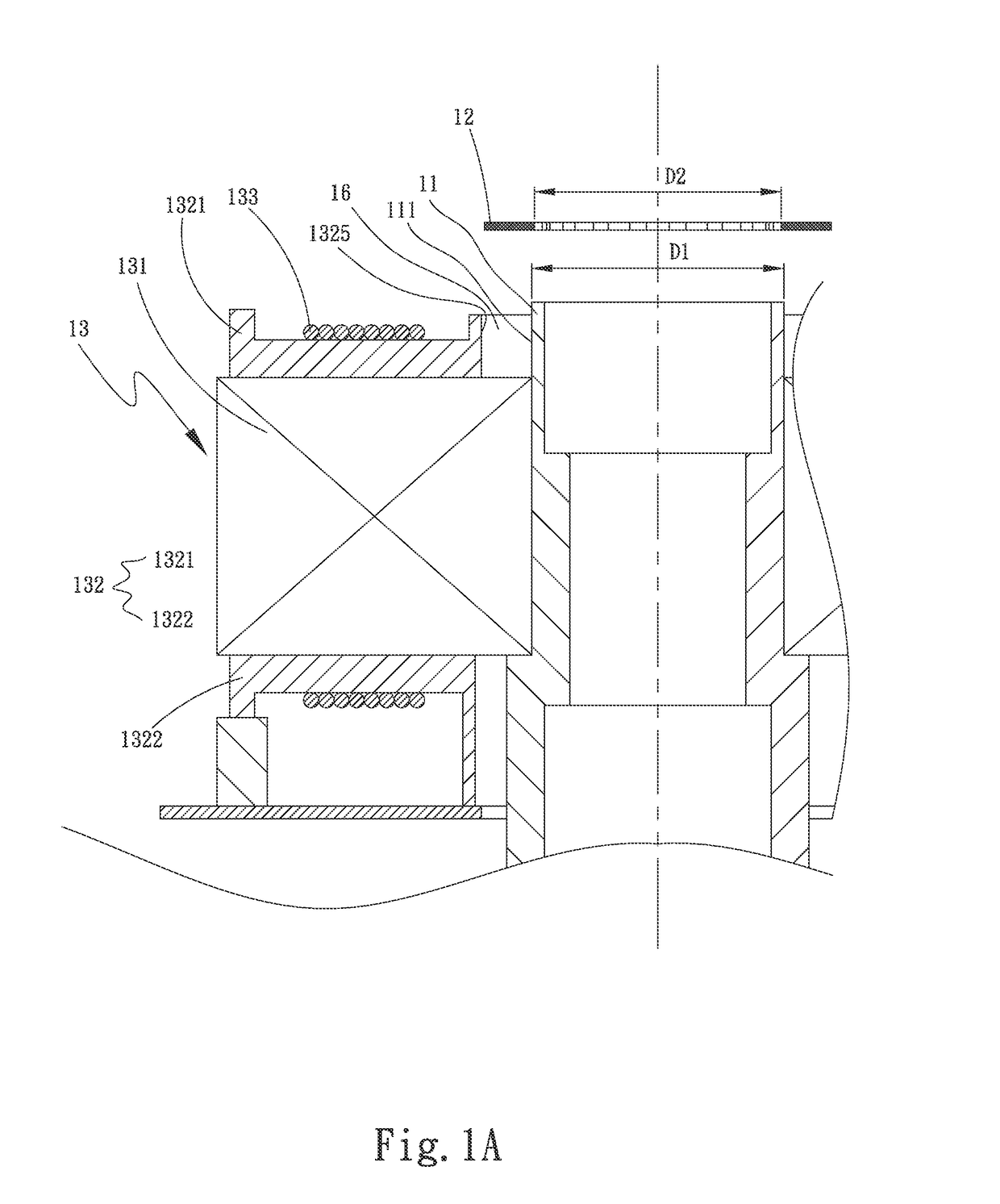
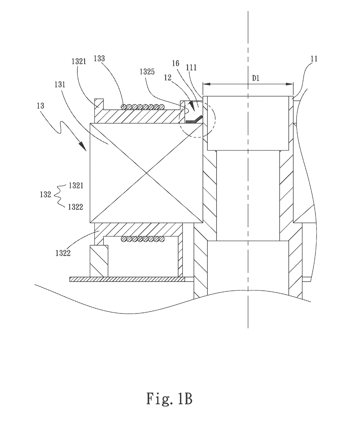
[0027]A stator fixing structure includes a tube and a fixing member. The tube has an outer surface, and both a stator set and the fixing member are fitted around the tube in a bottom-up sequence. The fixing member has a main body, which has a contact surface and an engaging unit. The engaging unit is circumferentially extended from the main body towards a center of the main body to form a plurality of free ends to tightly press against the outer surface of the tube. The contact surface is axially tightly in contact with the stator set to prevent the stator set from sliding.

[0028]Please refer to FIGS. 1A to 1B, which are fragmentary exploded and assembled sectional views, respectively, of a stator fixing structure acc...


PUM


Abstract

A stator fixing structure includes a tube and a fixing member. The tube has an outer surface, and both a stator set and the fixing member are fitted around the tube in a bottom-up sequence. The fixing member has a main body, which has a contact surface and an engaging unit. The engaging unit is circumferentially extended from the main body towards a center of the main body to form a plurality of free ends to tightly press against the outer surface of the tube. The contact surface is axially tightly in contact with the stator set to prevent the stator set from sliding.

Description

FIELD OF THE INVENTION[0001]The invention relates to the technical field of a motor, and more specifically, to a stator fixing structure that can be used in various electric motors which generate rotatable power.BACKGROUND OF THE INVENTION[0002]Generally speaking, a stator is fitted around a tube, which is located onto a center of a base, such that the stator is located onto the base. The tube is a hollow cylinder and has at least one bearing fitted therein. A rotor is extended through by a shaft to connect to the shaft, so the rotor is fixedly located onto the base and corresponding to the stator. The stator is fitted around the tube or located onto the base by gluing.[0003]However, using glue to connect the stator to tube or the base has the following disadvantages: (1) additional labor time is required in the whole manufacturing process, causing higher manufacturing costs, and it is apt to glue-overflowing; (2) when one component, such as the stator, is broken, the whole structur...

Claims


Application Information

Patent Timeline
IPC IPC(8): H02K1/18
CPCH02K1/185H02K1/187H02K2213/03
Inventor SUN, SUNG-WEILIU, REN-ZHENYE, ZE-SEN
Owner ASIA VITAL COMPONENTS SHENZHEN CO LTD
Why Eureka
Eureka Blog
Learn More