Ball joint device for a turbine engine

a turbine engine and ball joint technology, applied in mechanical equipment, sliding contact bearings, transportation and packaging, etc., can solve the problems of accelerated wear and damage, and achieve the effect of preserving connection, promoting unnecessary axial movement, and eliminating axial clearan

Active Publication Date: 2017-04-13
SN DETUDE & DE CONSTR DE MOTEURS DAVIATION S N E C M A
View PDF16 Cites 7 Cited by
  • Summary
  • Abstract
  • Description
  • Claims
  • Application Information

AI Technical Summary

Benefits of technology

[0009]The device according to the invention is therefore equipped with means for axially holding the shaft so that said shaft does not become disconnected from the lugs. Thus, even in the event of fracture of the shaft, these fractured parts are held and do not become dislodged from the openings in the lugs, which makes it possible to preserve the connection of the first and second members.
[0010]Moreover, the resilient member, which axially biases the ball joint on the side opposite the cover, makes it possible, after mounting, to eliminate axial clearance between the ball joint and two holding elements, for example in the form of bushings, that are arranged axially on either side of the ball joint and axially immobilise the ball joint on the shaft. Such an axial clearance is generally necessary for mounting the ball joint since, before the shaft is mounted, the ball joint must be positioned between the two lugs of the second member, once the holding elements have also been positioned by bringing them into the interior space extending between the two lugs. This clearance is detrimental during operation since it may promote unnecessary axial movement of the ball joint and accelerated wear thereof, of the shaft, or even also of the two holding elements. In other words, the resilient member ensures, during operation, the elimination of the axial ball-joint mounting clearance.

Problems solved by technology

This clearance is detrimental during operation since it may promote unnecessary axial movement of the ball joint and accelerated wear thereof, of the shaft, or even also of the two holding elements.

Method used


Image

  • Ball joint device for a turbine engine
  • Ball joint device for a turbine engine
  • Ball joint device for a turbine engine

Examples


Embodiment Construction

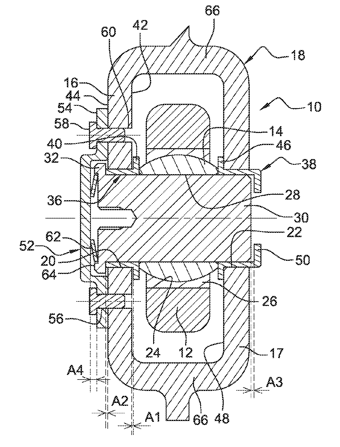
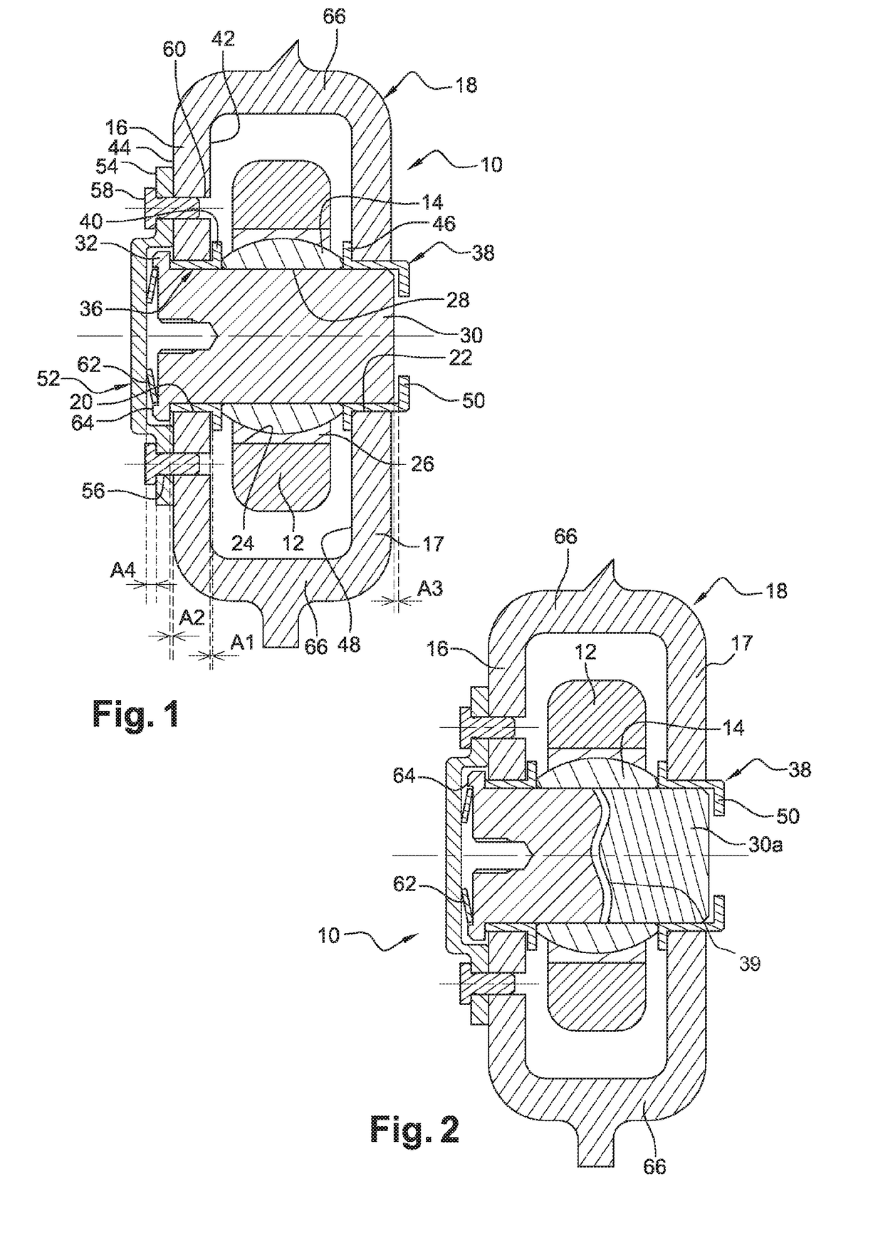
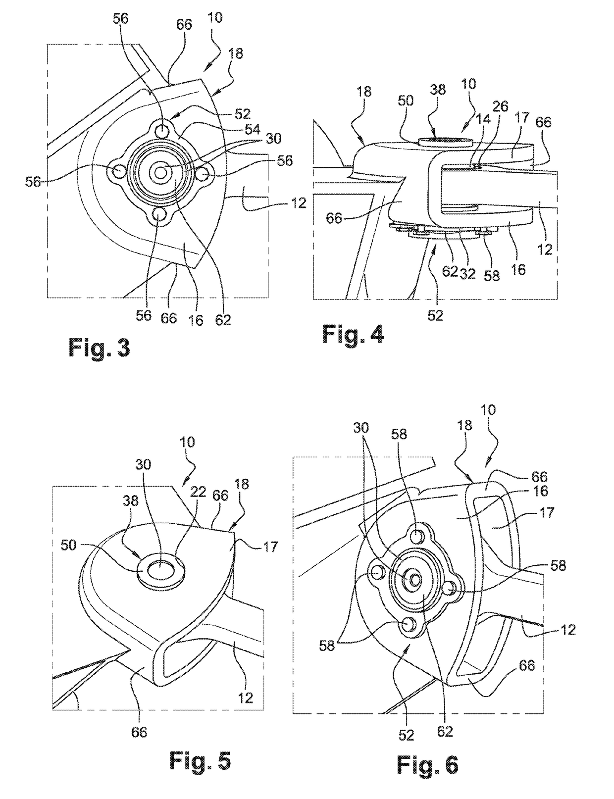
[0029]FIGS. 1 to 6 show a first embodiment of the ball joint device 10 according to the invention. This device 10 comprises a connecting rod 12, one end of which carries a ball joint 14 and is interposed between the two lugs 16, 17 of a clevis 18.

[0030]In the case of the suspension of a turbine engine from a strut, the clevis 18 is typically formed together with or fixed to a casing of the engine. The clevis 18 is of the female type and its two lugs 16, 17 are flat and parallel to each other, these lugs 16, 17 comprising coaxial openings 20, 22 having cylindrical internal walls.

[0031]The connecting rod 12 is connected to means for suspension on the strut and the end of said rod that can be seen in the drawing is flat and comprises an opening 24 having an internal cylindrical wall for mounting a cage 26 that is clamped in the opening and the internal spherical wall of which receives the ball joint 14, which is free to rotate in the cage 26. The ball joint 14 comprises a cylindrical b...


PUM


Abstract

The ball joint device (10) for suspending a turbine engine from a strut or suspending equipment on the body of a turbine engine. Said device comprises a first member (12), one end of which carries a ball joint (14) and is interposed between the two lugs (16, 17) of a second member (18), the ball joint comprising a bore (28) for the passage of a shaft (30), the ends of which shaft pass through openings (20, 22) in the lugs. A first (16) of the lugs comprises or carries first means for axially holding the shaft on the side opposite the ball joint, which means comprise a cover (52, 52′), and a second (17) of the lugs comprises or carries second means (38) for axially holding the shaft on the side opposite the ball joint. The device further comprises a resilient member (62, 62′) that is deformable under compression and is held by the cover, said resilient member (62, 62′) being designed to bias a support element (40), through which the shaft passes and which is in axial abutment on the ball joint (14), axially in a direction away from the cover.

Description

TECHNICAL FIELD[0001]The present invention relates to a ball joint device for suspending a turbine engine from a strut or suspending an item of equipment on the body of a turbine engine.PRIOR ART[0002]The prior art comprises in particular the documents FR-A1-2 887 853, EP-A1-0 357 504, JP-A-2003 205251 and JP H02 49797.[0003]A turbine engine is generally suspended from a strut by means of a yoke that is fixed to the body of the turbine engine, at the intermediate casing thereof. This yoke comprises clevises on which ends of connecting rods are hinged, the other ends of which rods are connected to means for suspending the turbine engine on the strut. Each connecting rod is in general hinged on a clevis by means of a ball joint device.[0004]In the prior art, each connecting rod has an end that carries a ball joint and is interposed between the two lugs of a clevis, the ball joint comprising a bore for the passage of a shaft, the ends of which pass through openings in the lugs of the c...

Claims


Application Information

Patent Timeline
Patent Type & Authority Applications(United States)
IPC IPC(8): F16C11/06B64D27/26F16C23/04F16C11/04
CPCF16C11/0614F16C11/045F16C2360/23F16C23/043B64D2027/268B64D27/26F16C2326/43F16C27/02F16C2229/00F16C11/06
Inventor FLORENT, NICOLAS MARCTESNIERE, MARC PATRICK
Owner SN DETUDE & DE CONSTR DE MOTEURS DAVIATION S N E C M A
Why Eureka
Try Eureka