Helmet-mounted thermal imaging system

a thermal imaging and helmet technology, applied in the field of helmet-mounted thermal imaging systems, can solve the problems that the mounting arrangement and positioning of the camera and the associated display have not been completely satisfactory in preserving a clear and natural field of view for the user-wearer, and achieve the effect of improving the image of obscured areas

Active Publication Date: 2008-05-06
SAGE TECH
View PDF16 Cites 71 Cited by
  • Summary
  • Abstract
  • Description
  • Claims
  • Application Information

AI Technical Summary

Benefits of technology

[0004]Accordingly, it is a general purpose and object of the present invention to provide an improved helmet-mounted camera system better capable of assisting emergenc...

Problems solved by technology

Although existing helmet-mounted thermal imaging systems have been generally successful in providing a hands-free visual display of the obscured site conditions, the mounted arrangement and positioning of their cameras and associated displays have no...

Method used


Image

  • Helmet-mounted thermal imaging system
  • Helmet-mounted thermal imaging system
  • Helmet-mounted thermal imaging system

Examples


Embodiment Construction

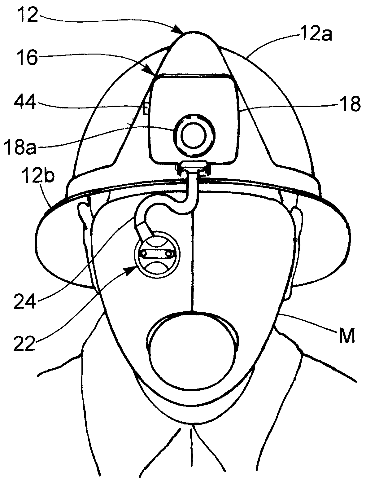
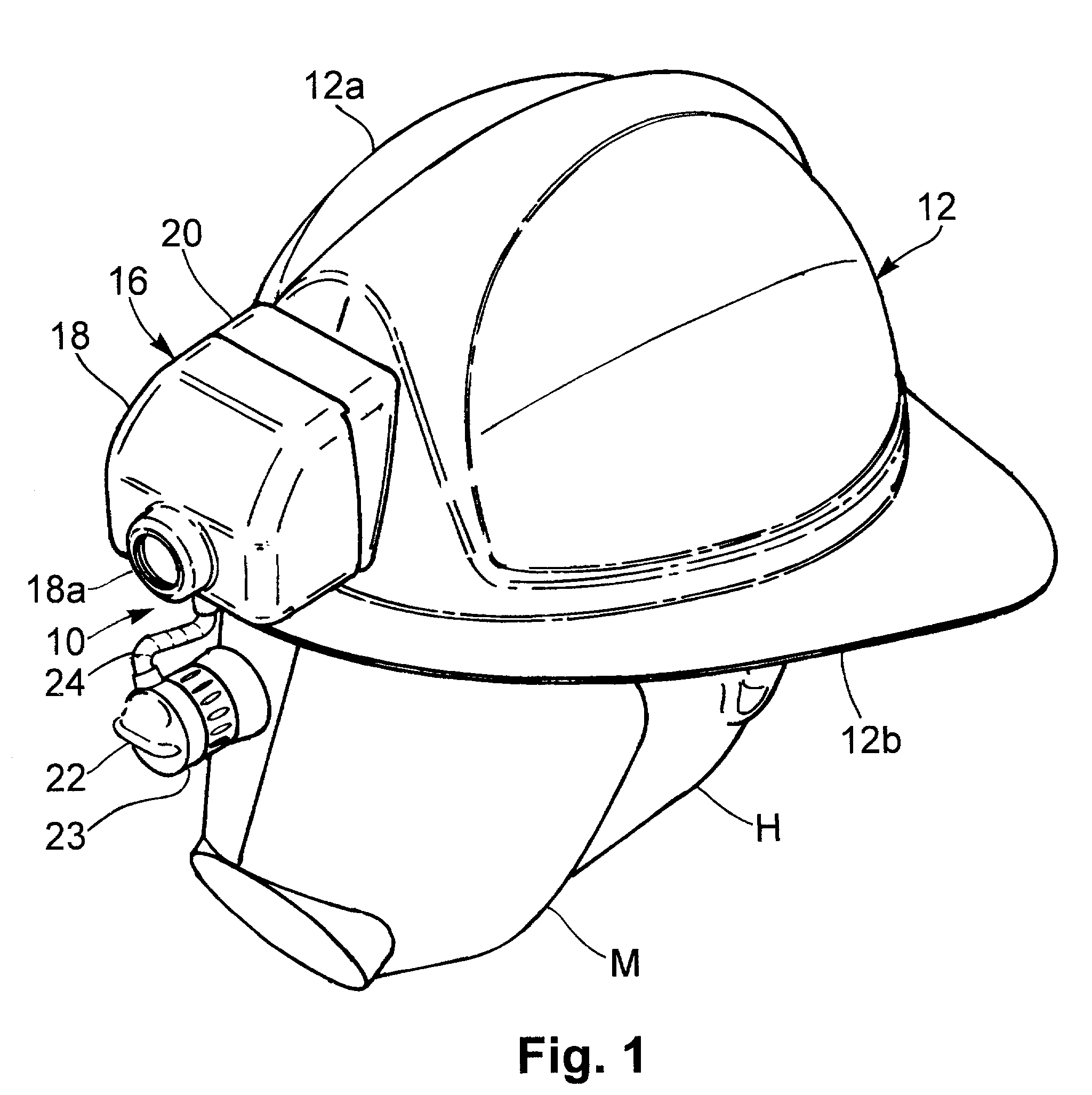
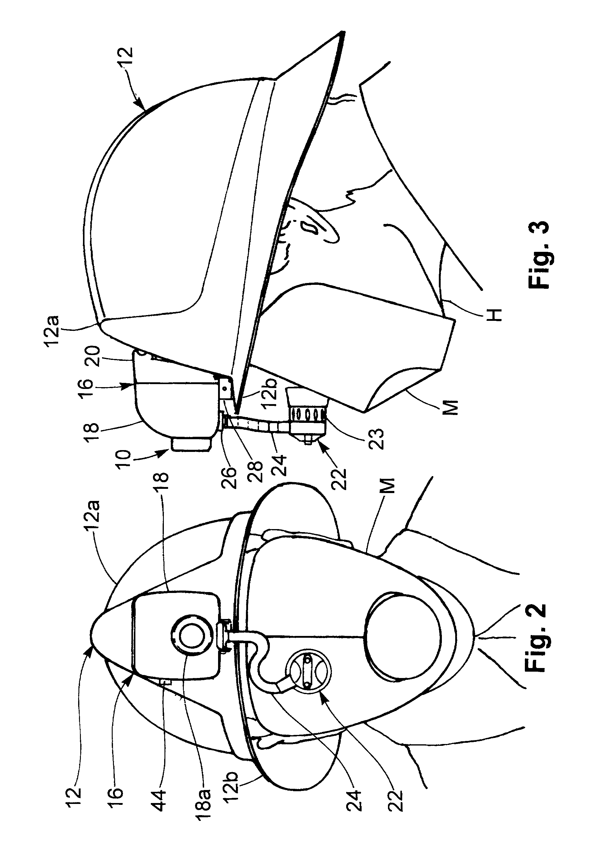
[0023]Referring now to the drawings and particularly to FIGS. 1-3, a thermal imaging camera system, generally designated 10, is shown assembled and mounted upon the front of a protective helmet 12 that is worn upon the head H of a firefighter or other emergency personnel. Further depicted in the present drawing figures is a protective mask M typically worn over the face of the firefighter in conjunction with the protective helmet 12. In accordance with the present invention, the thermal imaging camera system 10 comprises an infrared camera assembly 14, best viewed in FIGS. 4 and 5, that is fully contained within a protective housing 16, adapted to be releasably mounted to the brim 12b of the helmet 12 in a central position immediately forward of the helmet cap 12a. The protective housing 16 includes a front enclosure member 18 formed having a cavity, as described in greater detail below, to hold substantially all of the infrared camera assembly 14 in a forward facing position with a...


PUM


Abstract

An improved thermal imaging camera system is adapted to be releasably mounted to a protective helmet typically worn by a firefighter or other emergency personnel at an incident site. The present system comprises a thermal imaging camera assembly having a single eyepiece display flexibly coupled thereto, a protective housing for the camera assembly and a specially adapted mounting bracket assembly for releasably stationing the camera assembly and its protective housing in a central position on the helmet. The camera assembly further includes and integrates a miniaturized infrared camera unit with associated battery power supply and control electronics for high resolution image production. The single eyepiece display is flexibly coupled to the camera assembly and its housing by means of an articulated arm that accommodates positioning of the display in front of either the left or right eye of the user-wearer with or without an air mask or other protective interface being worn over the face of the user-wearer. The mounting bracket assembly includes a T-shaped base bracket having a rectangular head adapted to be fixed in a level position on the front of the helmet and a C-shaped upper bracket attached to the bottom of the housing and formed to slidingly engage the head of the base bracket thereby holding the camera system in proper position on the helmet. Spring-loaded detents on opposite sides of the head of the base bracket serve to lock the bracket assembly together by engaging the sides of the upper bracket and further allow manual disengagement therefrom so that the camera system may be quickly removed from the helmet and rapidly deployed on another similarly equipped helmet.

Description

BACKGROUND OF THE INVENTION[0001]The present invention relates to thermal imaging systems of the type applied for use in firefighting and search and surveillance operations, and more particularly to an improved helmet-mounted camera system that may be readily deployed and used to display a high resolution thermal image of an incident site directed to either eye of the user while maintaining direct visual contact of the user with the site to provide better visibility of the surrounding areas.[0002]In the conduct of firefighting and certain search and surveillance operations, it is critical to the success and safety of the operations that operating personnel be able to see as much of the incident site as possible and observe as much evidence of site conditions as one can gather aided and assisted by specially designed and adapted sensor devices. Such sensor devices have included thermal or infrared imaging cameras adapted to be worn in connection with a protective helmet for providing...

Claims


Application Information

Patent Timeline
IPC IPC(8): H04N5/225G02B27/00G02B27/01
CPCA42B3/042G02B27/0176H04N5/2251G02B2027/0138H04N5/33H04N23/50H04N23/63
Inventor OLITA, JULESMEDD, OWENSHERIDAN, WESLEY
Owner SAGE TECH
Why Eureka
Try Eureka