Screw

a screw and screw body technology, applied in the field of screws, can solve the problems of reducing the tapping force applied to the tapping process of the screw, and saving the labor of users when screwing the screw, and achieve the effect of removing the obstruction of the discharging chip

Inactive Publication Date: 2017-04-20
YANG HUI JU
View PDF10 Cites 20 Cited by
  • Summary
  • Abstract
  • Description
  • Claims
  • Application Information

AI Technical Summary

Benefits of technology

[0009]The main objective of the present invention is to provide a screw to eliminate obstruction of discharging chips of the conventional screw.

Problems solved by technology

In addition, an inclined angle of a thread wall of the thread part towards the tip is smaller than an inclined angle of the other thread wall of the thread, so twisting force applied to the tapping process of the screw is reduced and screwing of the screw is laborsaving for users.

Method used


Image

  • Screw
  • Screw
  • Screw

Examples


Embodiment Construction

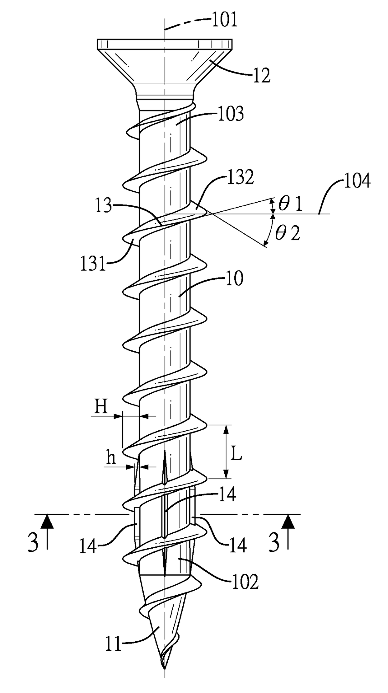
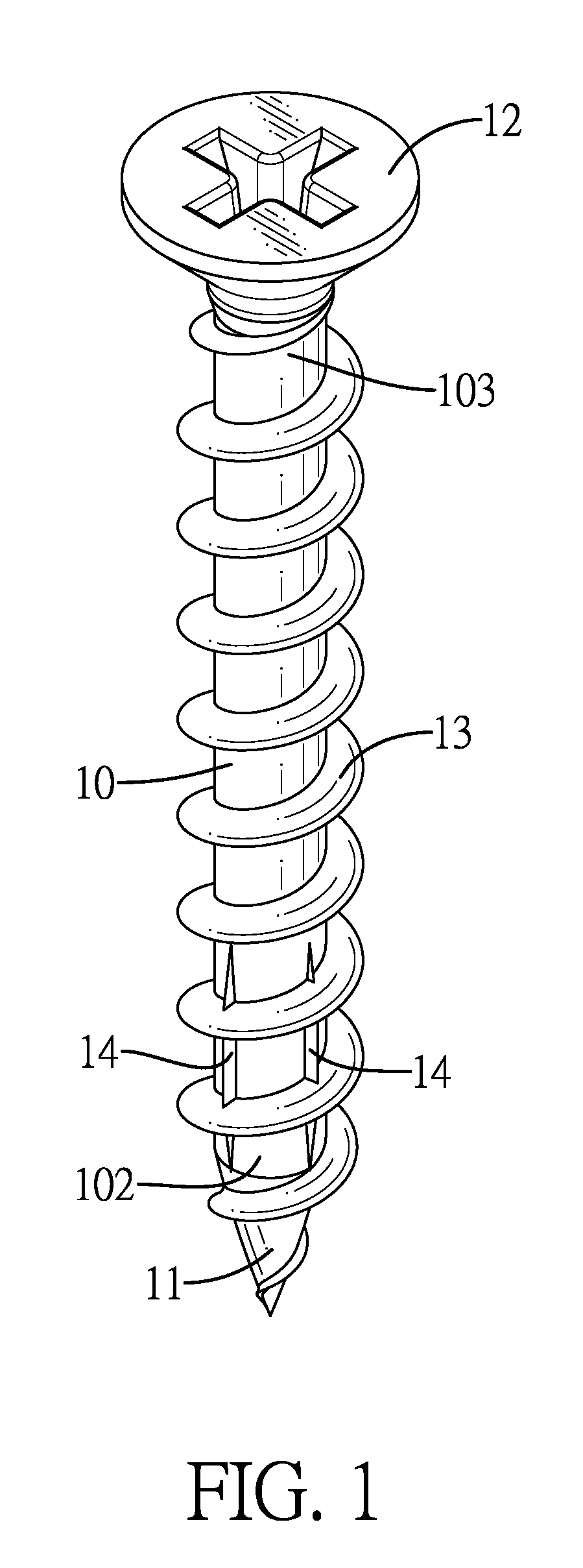
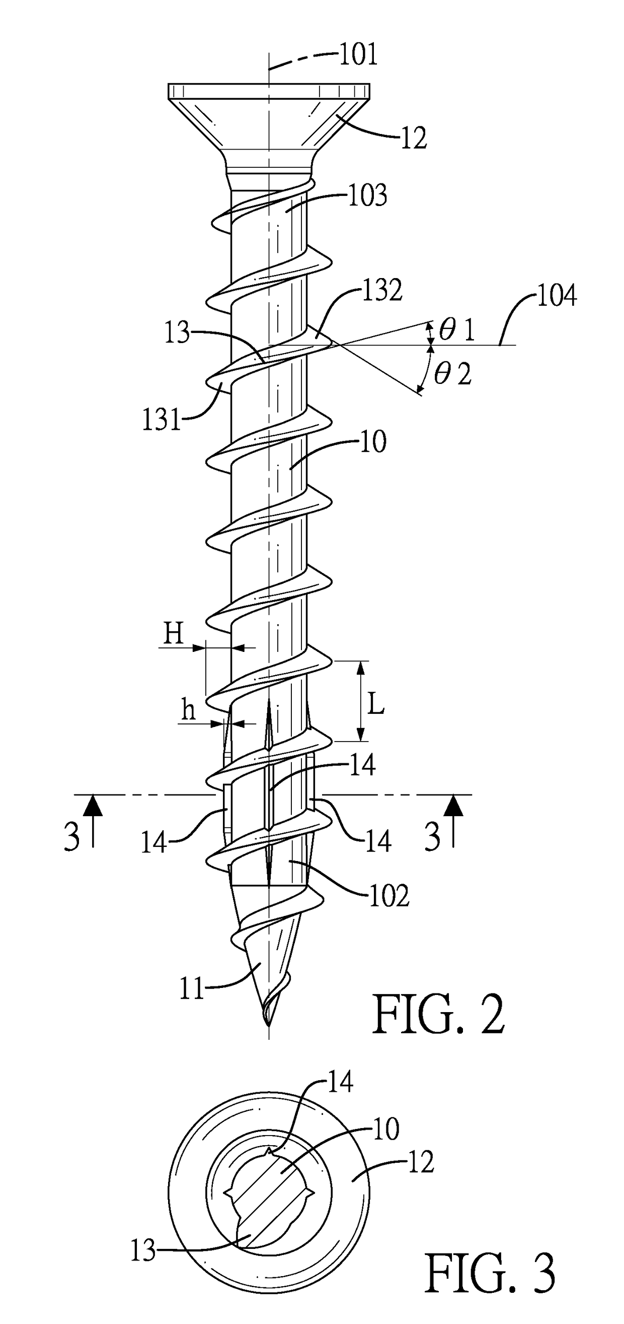
[0019]With reference to FIG. 1, an embodiment of a screw in accordance with the present invention comprises a circular rod 10, a tip 11, a tool connecting part 12, a thread part 13, and multiple protruding ribs 14.

[0020]With reference to FIGS. 1 to 2, the circular rod 10 has a centerline 101, a tail end 102, and a head end 103. The tail end 102 and the head end 103 are respectively formed on two ends of the circular rod 10 relative to the centerline 101 of the circular rod 10. The tip 11 is formed on the tail end 102 of the circular rod 10. The tool connecting part 12 is formed on the head end 103 of the circular rod 10 and a diameter of the tool connecting part 12 is bigger than a diameter of the circular rod 10. The tool connecting part 12 has a tool recess formed on a top surface of the tool connecting part 12. In a preferred embodiment, the tool recess is slotted, cross, polygonal or in any other shape for connecting a hand tool or an electric tool. The thread part 13 helically ...


PUM

PropertyMeasurementUnit
included angleaaaaaaaaaa
angleaaaaaaaaaa

Abstract

The screw comprises a circular rod, a tip, a tool connecting part, a thread part, and multiple protruding ribs. The circular rod has a centerline, a tail end, and a head end. The tip is formed on the tail end. The tool connecting part is formed on the head end. The thread part helically extends from an outer surface of the tip to an outer surface of the circular rod. The multiple protruding ribs are formed on an outer surface around the tail end and disposed in multiple thread pitches of the thread part from the tip. The multiple protruding ribs straightly extend on the circular rod and are parallel to the centerline, and provide a reaming effect to reduce resistance when the tip of the screw is screwed into the workpiece. So chips are smoothly discharged from the workpiece.

Description

BACKGROUND OF THE INVENTION[0001]1. Field of the Invention[0002]The present invention relates to a screw, especially a screw for screwing wooden workpiece.[0003]2. Description of the Prior Arts[0004]Multiple types of screws are designed according to various applications and functions. Taking a screw for screwing wooden workpiece for example, said screw has a circular rod, a tip, a tool connecting part, and a thread. The tip is formed on a tail end of the circular rod. The tool connecting part is formed on a head end of the circular rod. The thread helically extends from an outer surface of the tip to an outer surface of the circular rod.[0005]A hand tool or electric tool is connected to the tool connecting part of the screw by a user, and the tip of the screw is disposed towards the wooden workpiece. The screw is applied with twisting force by the hand tool or the electric tool to make the tip and the thread of the screw bore a hole and tap in the workpiece to be securely screwed wi...

Claims


Application Information

Patent Timeline
Patent Type & Authority Applications(United States)
IPC IPC(8): F16B25/10F16B25/00
CPCF16B25/103F16B25/0078F16B25/0015
Inventor YANG, HUI-JU
Owner YANG HUI JU
Why Eureka
Try Eureka