Central tire inflation system

a tire inflation system and tire inflation technology, applied in the direction of tire measurement, tyre parts, transportation and packaging, etc., can solve the problem that the target tire pressure inflation would require a so as to avoid unnecessary activation or repeated activation of the compressor

Active Publication Date: 2017-04-27
JAGUAR LAND ROVER LTD
View PDF4 Cites 7 Cited by
  • Summary
  • Abstract
  • Description
  • Claims
  • Application Information

AI Technical Summary

Benefits of technology

[0008]to control the CTIS to deflate said tire from the interim tire pressure to the target tire pressure. As the interim tire pressure is higher than the target tire pressure, the processor can control the CTIS to deflate the tire to achieve the target tire pressure. When inflating the tire, the need to perform multiple inflation processes can be obviated, at least in certain embodiments. Conversely, when deflating the tire, the need to perform inflation (for example due to overshooting the target tire pressure) can be obviated, at least in certain embodiments. The inflation or deflation strategy described herein allows the target tire pressure to be achieved while avoiding unnecessary activation or repeated activation of a compressor. In particular, tire inflation to the target tire pressure would require a repeated activation of the compressor if the target tire pressure has been undershot. Likewise, tire deflation to the target tire pressure would require activation of the compressor if the target tire pressure has been overshot.
[0009]The processor can be configured to receive a signal representative of a measured first tire pressure. The first tire pressure can correspond to an initial tire pressure before inflation or deflation to the interim tire pressure. The first tire pressure can be used to control the inflation or deflation of said tire to said interim tire pressure. For example, based on said first tire pressure, the processor can control the time period over which compressed air is supplied to the tire or vented from the tire.
[0010]The processor can be configured to receive a signal representative of a measured second tire pressure. The second tire pressure can correspond to the tire pressure after the tire has been inflated or deflated to said interim tire pressure. The second tire pressure should be substantially equal to the interim tire pressure, but system losses or inefficiencies may result in discrepancies. The second tire pressure can be used to control the deflation of said tire from said interim tire pressure to said target tire pressure. For example, based on said second tire pressure, the processor can control the time period over which compressed air is vented from the tire to achieve the target tire pressure.

Problems solved by technology

In particular, tire inflation to the target tire pressure would require a repeated activation of the compressor if the target tire pressure has been undershot.

Method used


Image

  • Central tire inflation system
  • Central tire inflation system
  • Central tire inflation system

Examples


Embodiment Construction

[0055]In the following description and in the drawings, reference letters are used to collectively or un-specifically identify equivalent or essentially equivalent components. Where necessary, a specific component in a collection of equivalent or essentially equivalent components is identified by suffixing a reference letters in subscript format.

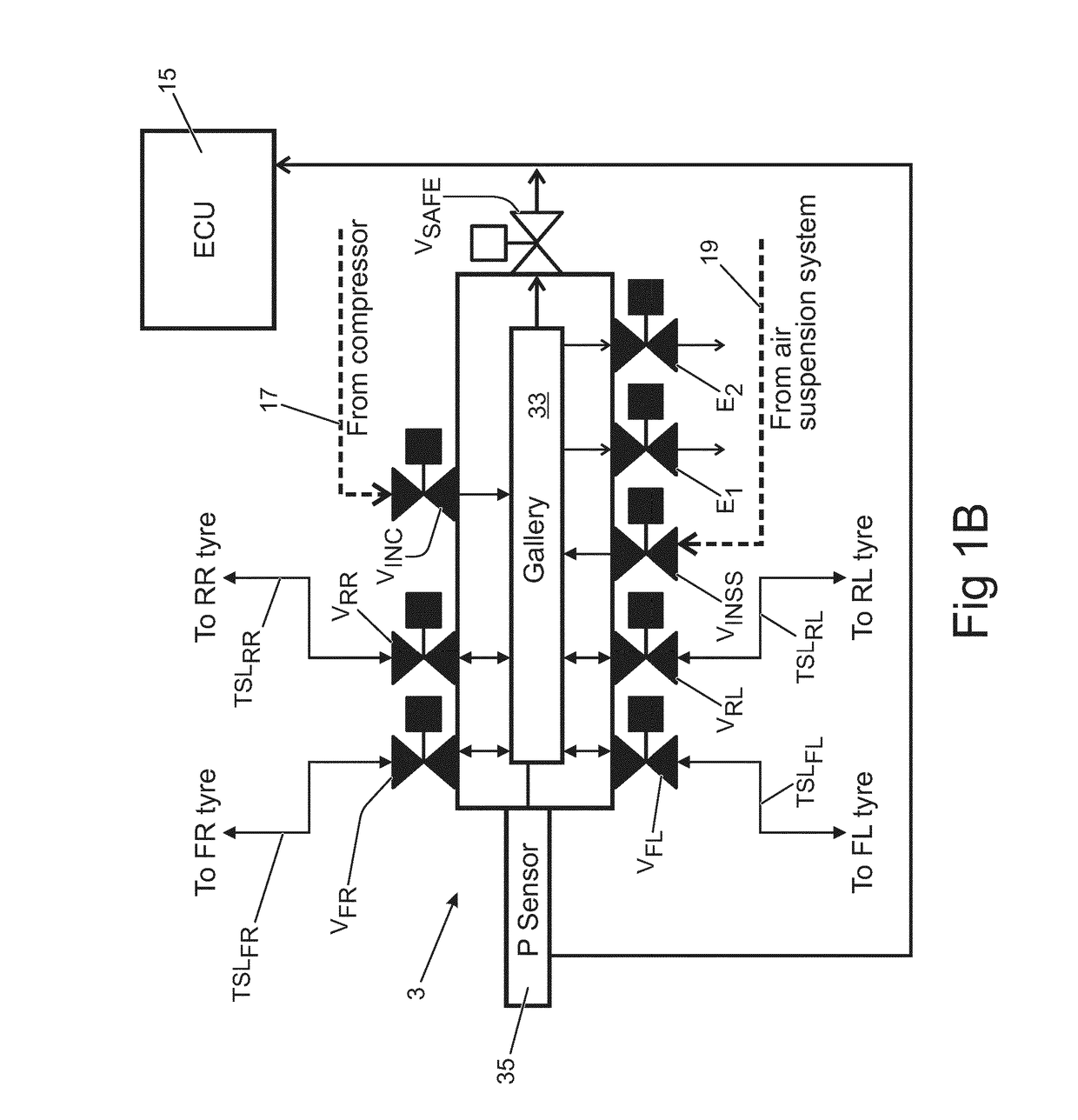
[0056]A central tire inflation system (CTIS) 1 in accordance with an embodiment of the present invention will now be described with reference to the accompanying Figures. As shown schematically in FIG. 1A, the CTIS 1 is installed in a vehicle VH having four wheels W each having a tire T mounted on a wheel hub (not shown). The wheels W (and the tires T) are identified herein based on their relative position on the vehicle VH, namely: front left (FL), front right (FR), rear left (RL) and rear right (RR). This nomenclature is employed to identify the components of the CTIS 1 associated with the respective tires T. The front tires TFR, TFL are m...


PUM


Abstract

A processor for controlling operation of a central tire inflation system (CTIS) to change a tire pressure of a tire of a vehicle is configured to control the CTIS to inflate or deflate the tire to a predetermined tire pressure which is above a target tire pressure for the tire. The processor then controls the CTIS to deflate the tire until the target tire pressure is reached. In this manner, a second tire inflation operation to achieve the target tire pressure in the tire can be avoided.

Description

TECHNICAL FIELD[0001]The present invention relates to a processor for controlling operation of a central tire inflation system (CTIS) to change a tire pressure of a tire of a vehicle; to an electronic control unit (ECU); to a CTIS; to a vehicle; to a method; and to a computer program product.BACKGROUND OF THE INVENTION[0002]Central tire inflation systems (CTIS) were originally developed for military applications, in particular for military applications concerning off-road military wheeled trucks and trailers. However, CTIS are nowadays incorporated into non-military vehicles such as specialist construction equipment and some agricultural vehicles.[0003]A CTIS typically comprises a compressed air source located on-board the vehicle and connected to one or more tires. Tire pressure can therefore be adjusted by operating the CTIS. The CTIS delivers compressed air to tire supply lines. In some examples, the supply lines are integrated into the vehicle axles. Various valves are provided ...

Claims


Application Information

Patent Timeline
Patent Type & Authority Applications(United States)
IPC IPC(8): B60C23/00B60C23/04
CPCB60C23/003B60C23/0408B60C23/002B60C23/00318B60C23/00354B60C23/00372B60C23/00B60C23/001
Inventor KING, PAULDUNNING, EMMA-CLAIRELESBIREL, ROBBIEDODU, MAELLETRAN, THUY-YUNGLAANEMETS, LAURWOODLEY, JONATHAN
Owner JAGUAR LAND ROVER LTD
Why Eureka
Try Eureka