Combination radiant and forced air climate control system

a technology of climate control system and control system, which is applied in the direction of domestic cooling equipment, heating types, instruments, etc., can solve the problems of inability of radiant heating system to quickly heat a room, inability of forced air controller to communicate and coordinate heating functions, and dramatic drop in temperature within one heating zon

Inactive Publication Date: 2005-10-25
KRUMNOW MARK J
View PDF39 Cites 78 Cited by
  • Summary
  • Abstract
  • Description
  • Claims
  • Application Information

AI Technical Summary

Benefits of technology

[0009]The present invention is a controller for a climate control system that includes a primary heat source and a forced air system that provides a secondary heat source, primary and secondary cooling, and humidity control. The controller of the present invention controls the operation of the primary heat source, the secondary heat source and the cooling unit such that the single controller can operate the three separate systems in an efficient manner to control the temperature within a residence or small business.

Problems solved by technology

Although radiant heating systems are effective at maintaining a very constant temperature within a heating environment, radiant heating systems often suffer from the inability to quickly heat a room upon a sudden demand for heat, such as when the outside temperature drops dramatically, when the radiant heating system is initially turned on, or when a window has been left open and the temperature within one of the heating zone drops dramatically.
One primary reason for this is the inability for the forced air controller to communicate and coordinate the heating function with the controller for the radiant heating system.
As discussed above, one draw back of a radiant heating system is the inability of the radiant heating system to quickly elevate the temperature in the building to the desired temperature upon a sudden demand for heat.
Although the radiant heating system is able to elevate the temperature in a building a few degrees in an acceptable amount of time, situations which require a large temperature rise require an increased amount of time compared to a forced air heating system.

Method used


Image

  • Combination radiant and forced air climate control system
  • Combination radiant and forced air climate control system
  • Combination radiant and forced air climate control system

Examples


Embodiment Construction

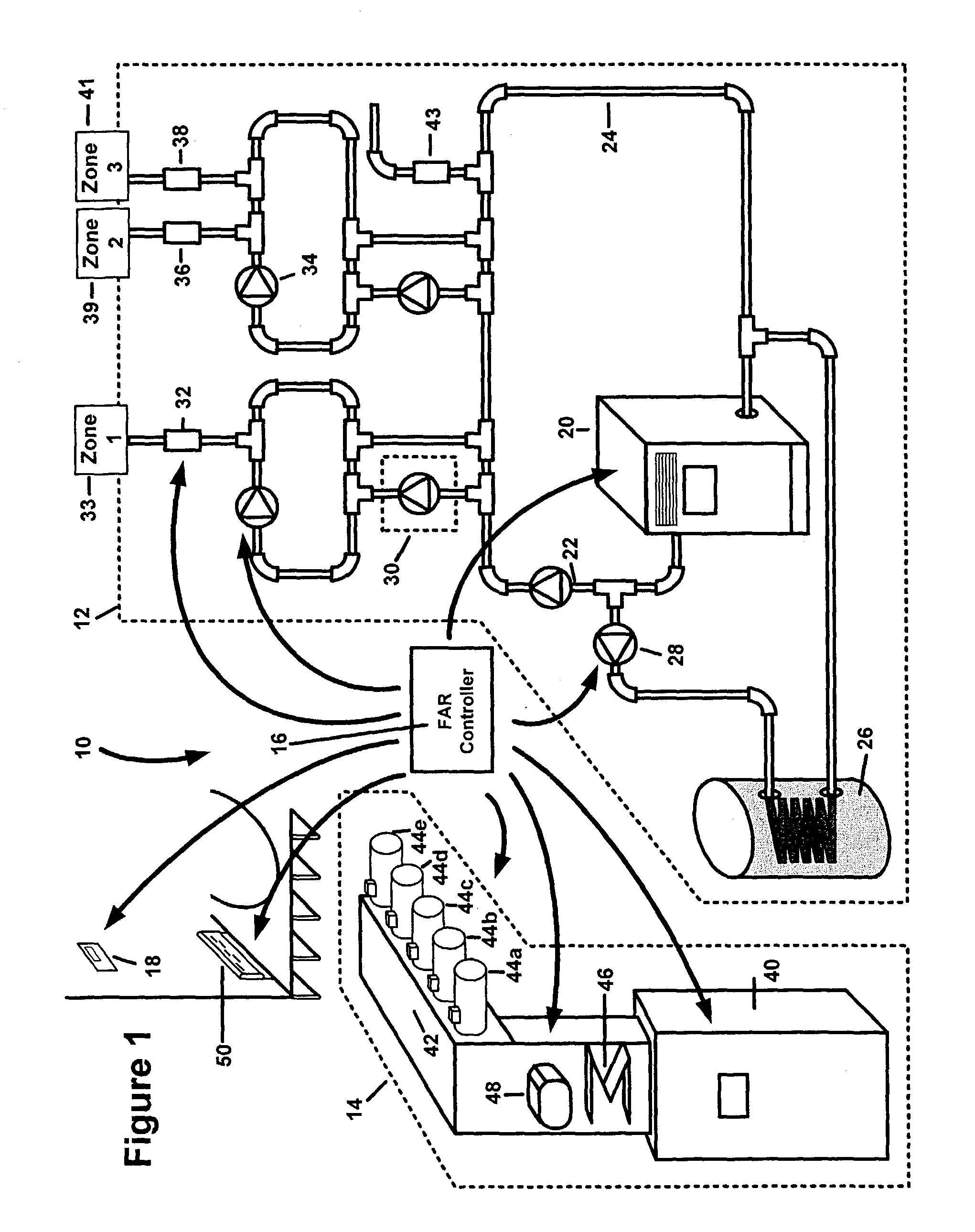
[0033]Referring first to FIG. 1, thereshown is a climate control system 10 of the present invention for a residence or small business. The climate control system 10 of the present invention includes a primary radiant heating system 12 and a forced air HVAC system 14. Both the radiant heating system 12 and the forced air HVAC system 14 are zoned systems that have the ability to independently provide heating and / or cooling to a plurality of individual zones. It should be understood that each zone is typically a room or group of rooms in the residence or small business.

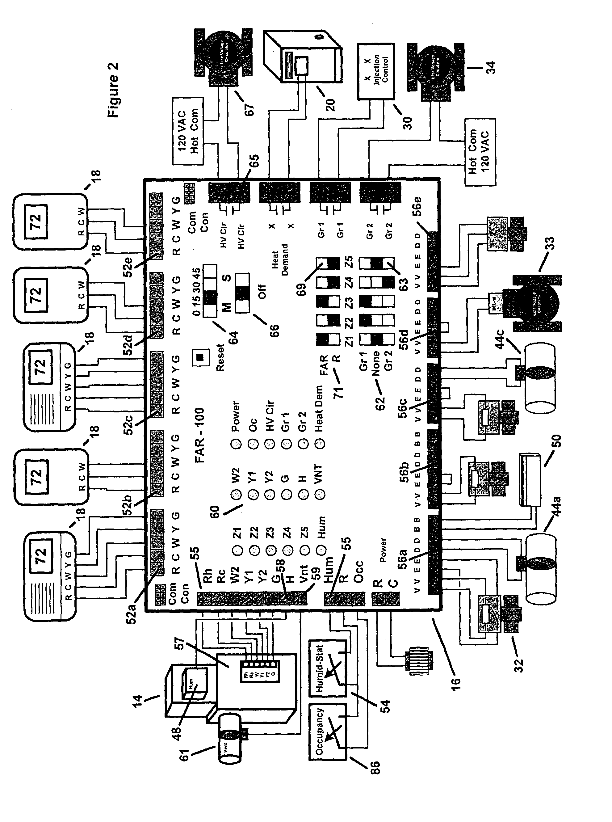
[0034]In accordance with the present invention, both the radiant heating system 12 and the forced air HVAC system 14 are controlled and operated by a single controller 16. The single controller 16 is also connected to a plurality of individual single stage zone thermostats 18 that allow the occupants to set a desired temperature for the individual zone. The zone thermostats 18 each generates a heating demand signal or a ...


PUM


Abstract

A method and controller for controlling the operation of a zoned climate control system including a primary heat source, a secondary heat source, a cooling unit, and a humidifier unit. The controller is configured to receive both heating demand signals and cooling demand signals from a plurality of zone thermostats positioned throughout the residence. Upon receiving a heating demand signal, the controller operates the primary heat source to provide heat to the zone issuing the heating demand signal. The controller determines whether the primary heat source satisfies the heating demand signal within a maximum heating period. If the heating demand is not satisfied within this period, the controller activates the secondary heat source to supplement the heat being supplied by the primary heat source.

Description

CROSS-REFERENCE TO RELATED APPLICATION[0001]The present application is based on and claims priority to U.S. patent application Ser. No. 09 / 769,860, filed on Jan. 25, 2001, issued as U.S. Pat. No. 6,575,233 on Jun. 10, 2003.BACKGROUND OF THE INVENTION[0002]The present invention relates to a controller and method of operating a climate control system including a primary and a secondary heating and cooling source with humidity control. More specifically, the present invention is a controller and method of providing heating and cooling to a zoned residence or building, from a primary source of heat, such as a radiant heating system, and a secondary source of heat, such as a forced air HVAC system. The HVAC system preferably provides primary and secondary cooling as well as humidity control.[0003]Many small businesses and homes utilize a zoned radiant heating system to heat the individual zones during periods of cold outside temperatures, such as during the winter months. In a radiant he...

Claims


Application Information

Patent Timeline
Patent Type & Authority Patents(United States)
IPC IPC(8): G05D27/00G05D27/02
CPCG05D27/02
Inventor KRUMNOW, MARK J.
Owner KRUMNOW MARK J
Why Eureka
Try Eureka