Cord winding mechanism for a cordless window blind

a cordless and window blind technology, applied in the field of window blinds, can solve the problems of easy damage, inability to use the winder b>90/b> on mini-blinds, and complicated guiding mechanisms

Active Publication Date: 2017-05-25
LEI ZHENBANG +1
View PDF3 Cites 7 Cited by
  • Summary
  • Abstract
  • Description
  • Claims
  • Application Information

AI Technical Summary

Benefits of technology

[0005]Therefore, a cord winding mechanism is provided, which orderly wind blind cords and assure same wound lengths of the blind cords of different winders controlled by the cord winding mechanism.

Problems solved by technology

However, the cord guiding mechanism is complicated and costly, and is easily damaged.
However, the winder 90 generally has a large volume, and thus, the winder 90 cannot be used on mini-blinds.

Method used


Image

  • Cord winding mechanism for a cordless window blind
  • Cord winding mechanism for a cordless window blind
  • Cord winding mechanism for a cordless window blind

Examples


Embodiment Construction

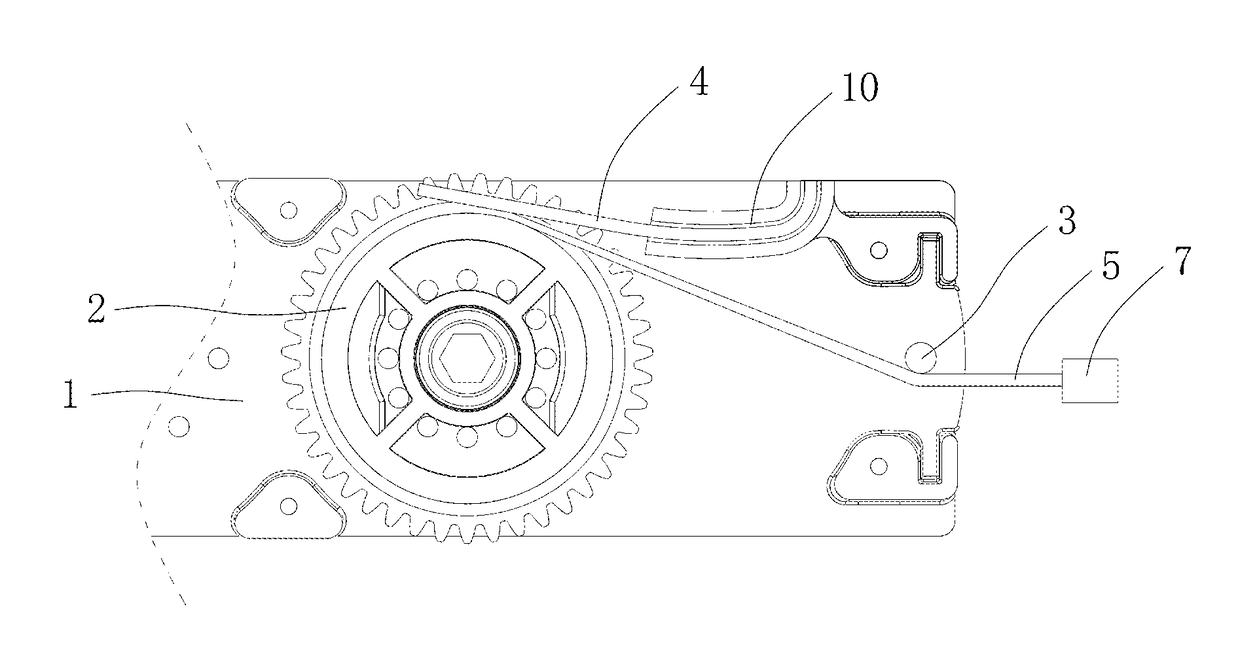
[0015]Referring to FIG. 1, a first embodiment of a cord winding mechanism for a cordless window blind 7 includes a base 1, a cord winder 2, a cord guiding assembly, and an elastic press member 4. The cordless window blind 7 is fixed with a blind cord 5.

[0016]The base 1 is plate-shaped. The cord winder 2 is rotatably mounted to a side surface of the base 1. The base 1 defines a substantially L-shaped groove 10. A first part of the groove 10 extends toward a side of the base 1, and a second part of the groove 10 extends from a bottom end of the first part of the groove 10 and toward the cord winder 2. The cord winder 2 is substantially H-shaped, and defines an annular slot 20 (same to the slot 20 labeled in FIG. 5) in a circumference of the cord winder 2.

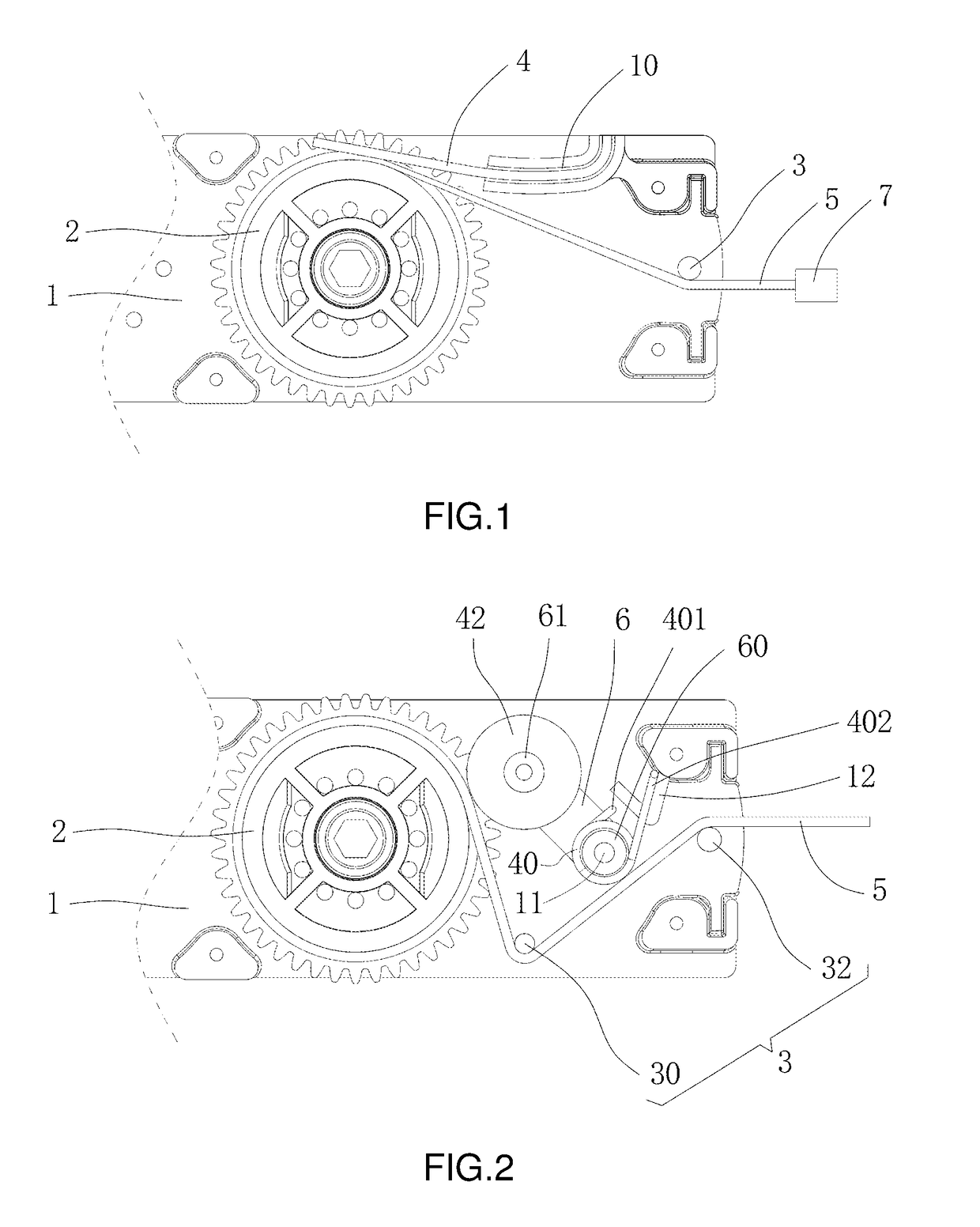
[0017]In the first embodiment, the cord guiding assembly includes a guiding wheel 32 rotatably mounted to the side surface of the base 1. An axis of the guiding wheel 32 is parallel to an axis of the cord winder 2. The elastic press m...


PUM


Abstract

A cord winding mechanism for a blind cord with a first end fixed to a window blind includes a base, a cord winder rotatably mounted to the base, a cord guiding assembly mounted to the base, and an elastic press member mounted to the base. The cord winder defines an annular slot to wind the blind cord layer by layer. The cord guiding assembly is abutted against an unwound portion of the blind cord between the cord winder and the window blind. A second end of the blind cord is fixed to an end of the cord winder in the slot. The press member is elastically abutted against a portion of the blind cord just separate from the cord winder.

Description

BACKGROUND OF THE INVENTION[0001]The present invention relates to window blinds and, more particularly to a cord winding mechanism for a cordless window blind.[0002]A cordless window blind is operable to raise and lower slats through elastic devices, without manually operating blind cords. Common cordless window blinds include shutters, honeycomb blinds, and Roman blinds. The cordless window blinds hide blind cords inside the blinds, and install winders on tops of the blinds to collect the blind cords, thus winding or unwinding the blind cords to raise or lower the blinds.[0003]FIG. 6 shows a conventional H-shaped winder 80. A blind cord 5 is wound round the winder 80 in a slot 82 of the winder 80. The H-shaped winder 80 generally operates in one of two operation modes, one of which is randomly winding blind cords and the other of which is adding a complicated cord guiding mechanism. When randomly winding blind cords, the blind cord 5 is wound without guide, thereby, the blind cord ...

Claims


Application Information

Patent Timeline
Patent Type & Authority Applications(United States)
IPC IPC(8): E06B9/36B65H75/26E06B9/322E06B9/26E06B9/382B65H75/44E06B9/24
CPCE06B9/368B65H75/4415B65H75/26E06B9/24E06B2009/3222E06B9/382E06B9/322B65H2701/35E06B9/26
Inventor LEI, ZHENBANGLEI, XINBANG
Owner LEI ZHENBANG
Why Eureka
Try Eureka