Roll-type take-up device

A winding device and roller technology, which is applied in the direction of winding strips, transportation and packaging, and transportation of filamentous materials, etc., can solve the problems of damage to the winding object, easy separation from the winding roller, and disordered winding.

Inactive Publication Date: 2015-03-25
CHANGZHOU CHANGYUAN NONWOVENS PROD
View PDF0 Cites 3 Cited by
  • Summary
  • Abstract
  • Description
  • Claims
  • Application Information

AI Technical Summary

Problems solved by technology

[0002] During the winding process of cloth or yarn, a winding roller is required for winding and winding. The existing winding device is a pair of supports, and a rotatable winding roller is arranged between the pair of supports. The outer diameters of the rollers are the same, so that during the winding process, the rolled cloth or yarn is easy to leave the winding roller, and the winding is chaotic; and during the winding process, in the case of power failure, the winding roller Under the action of inertia, it will continue to rotate, and the yarn or cloth will continue to be wound, which will easily cause damage to the wound object, and the winding will be relatively fluffy

Method used


Image

  • Roll-type take-up device
  • Roll-type take-up device

Examples


Embodiment Construction

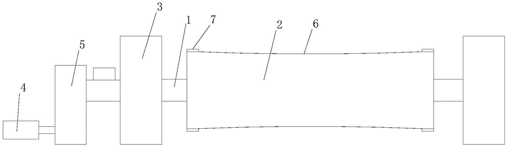
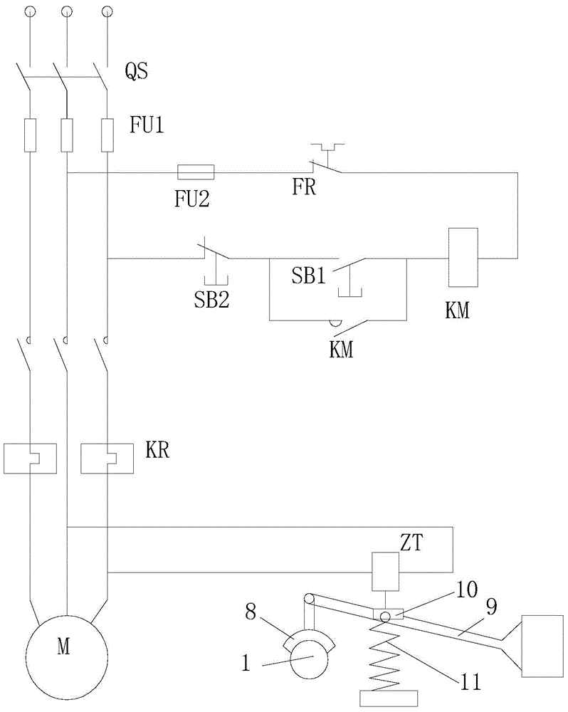
[0013] The present invention will be further described below in conjunction with accompanying drawing;

[0014] see figure 1 , figure 2 As shown, the roll-type winding device includes a winding shaft 1, a winding roller 2 that is arranged on the winding shaft and rotates with the winding shaft, and the two ends of the winding roller are respectively rotatably arranged on a support 3 through bearings, and drive The driving mechanism for the rotation of the winding roller. The driving mechanism includes a motor 4 and a speed reducer 5 between the winding roller and the motor. The shape is an arc surface, and the lowest surface of the arc surface coincides with the middle position of the winding roller. In the specific implementation, the difference between the most concave part and the most edge of the concave shape is between 1mm and 5mm, so that the winding can be guaranteed. orderly, there will be no detachment phenomenon, and it will not cause all the rewinding objects to...


PUM


Abstract

The invention relates to a roll-type take-up device. The roll-type take-up device comprises a take-up shaft, a take-up roll which is arranged on the take-up shaft and rotates along with the take-up shaft, and a drive mechanism, wherein the two ends of the take-up roll are rotationally arranged on supports; the drive mechanism is used for driving the take-up roll to rotate and comprises a motor and a reducer between the take-up roll and the motor; the outer surface of the take-up roll is concave towards a take-up roll body; the roll-type take-up device further comprises a locking system which locks the take-up shaft under an outage state. The take-up roll winds a wound object, as the surface of the take-up roll is in a concave shape, the wound object has the tendency of being wound to the middle of the take-up roll in the take-up process, and the problem that the wound object disengages from the take-up roll is avoided. In addition, when power fails, the locking system will lock the take-up shaft, the take-up roll is prevented from continuing to carry out take-up under the inertia effect, and the wound object will not be damaged.

Description

technical field [0001] The invention relates to a roll type winding device. Background technique [0002] During the winding process of cloth or yarn, a winding roller is required for winding and winding. The existing winding device is a pair of supports, and a rotatable winding roller is arranged between the pair of supports. The outer diameters of the rollers are the same, so that during the winding process, the rolled cloth or yarn is easy to leave the winding roller, and the winding is chaotic; and during the winding process, in the case of power failure, the winding roller Under the action of inertia, it will continue to rotate, and continue to wind up the yarn or cloth, which is easy to cause damage to the wound object, and the winding is relatively fluffy. Contents of the invention [0003] In view of the above technical problems, the object of the present invention is to provide a roller type winding device with simple structure and reasonable design, which can en...

Claims


Application Information

Patent Timeline
Patent Type & Authority Applications(China)
IPC IPC(8): B65H27/00B65H23/06B65H18/10B65H54/74
Inventor 徐媛
Owner CHANGZHOU CHANGYUAN NONWOVENS PROD
Why Eureka
Try Eureka