Vehicle rear portion structure

a rear portion and rear portion technology, applied in the direction of cell components, cell components, propulsion by batteries/cells, etc., can solve the problems of large displacement (amplitude) of the boundary portion between the low floor portion and the step wall portion, and the potential for stress to concentrate in the boundary portion, so as to achieve efficient enhancement of the vertical direction rigidity of the boundary portion between the low floor portion and the step wall portion, and the effect of reducing stress

Active Publication Date: 2017-06-29
TOYOTA JIDOSHA KK
View PDF1 Cites 15 Cited by
  • Summary
  • Abstract
  • Description
  • Claims
  • Application Information

AI Technical Summary

Benefits of technology

[0016]According to the vehicle rear portion structure pertaining to the third aspect, the plural reinforcement members are placed an interval apart from each other in the vehicle width direction. Because of this, the vehicle vertical direction rigidity of the boundary portion between the low floor portion and the step wall portion ...

Problems solved by technology

However, if the battery is installed on the low floor portion of the vehicle rear floor, in a case where, for example, the vehicle rear floor vibrates in the vehicle vertical direction as the vehicle travel...

Method used


Image

  • Vehicle rear portion structure
  • Vehicle rear portion structure
  • Vehicle rear portion structure

Examples


Embodiment Construction

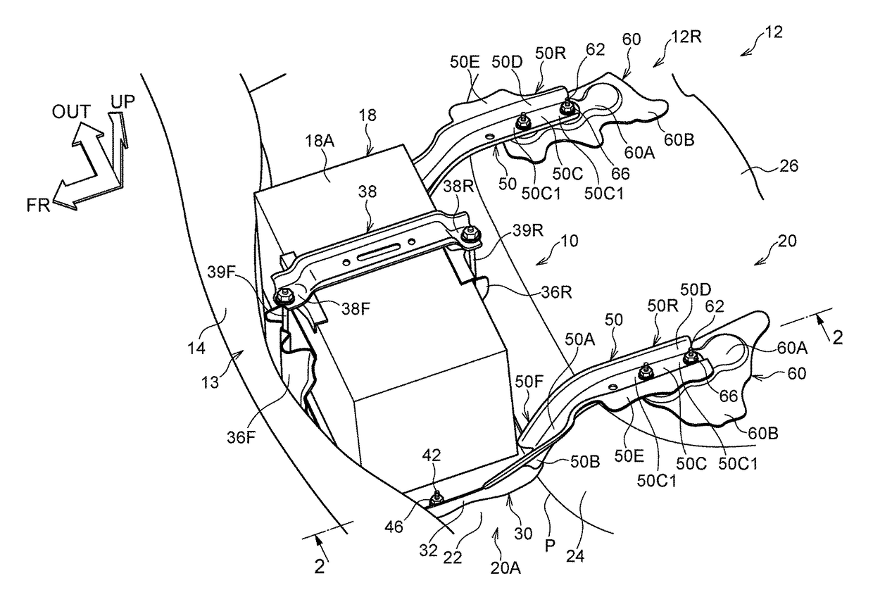
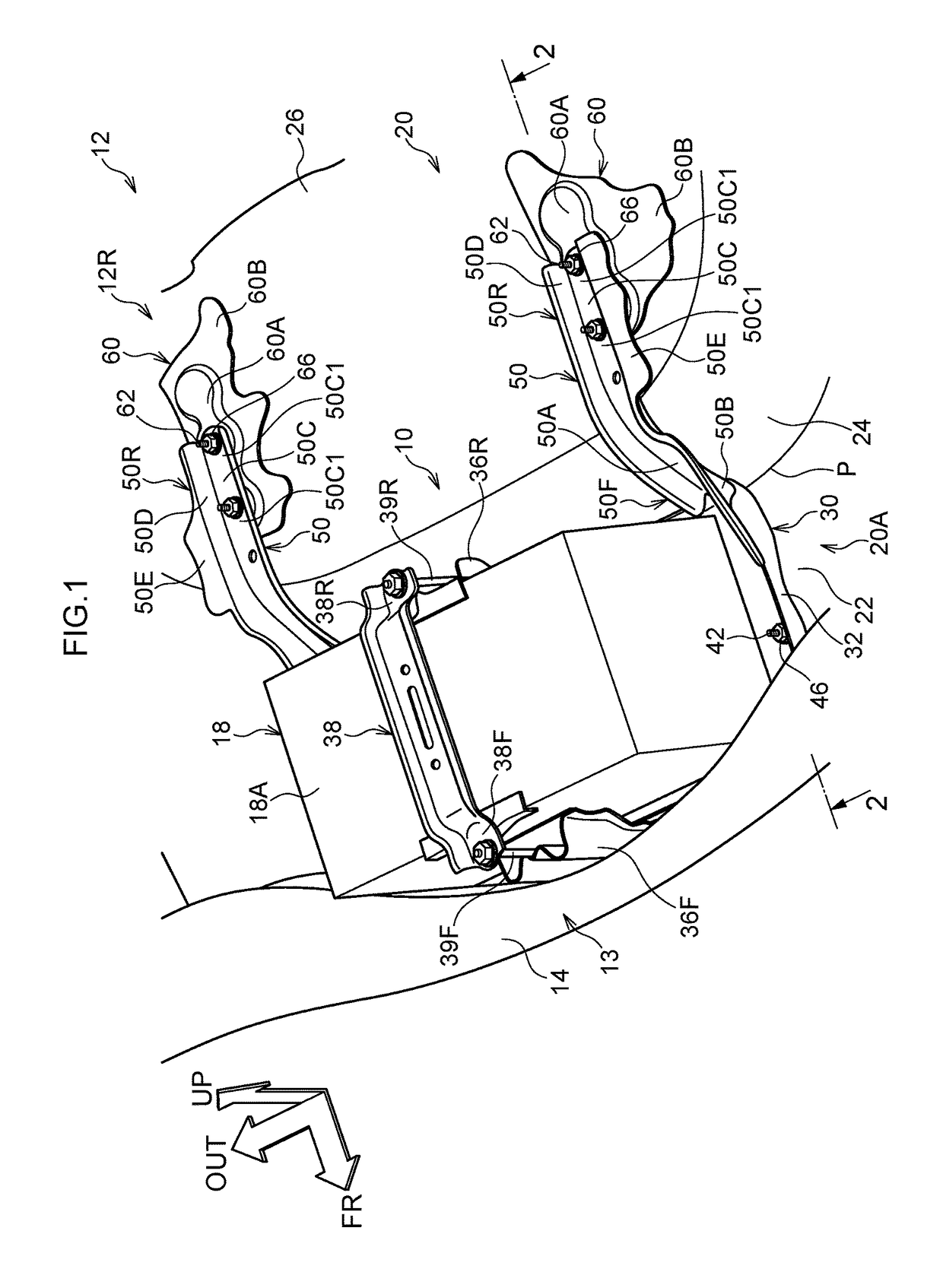
[0025]A vehicle rear portion structure pertaining to an embodiment of the present disclosure will be described below with reference to the drawings. It should be noted that arrow FR appropriately shown in the drawings indicates a vehicle front side (a front side in a vehicle front-rear direction) and arrow UP indicates a vehicle upper side (an upper side in a vehicle vertical direction). Furthermore, arrow OUT indicates an outer side in a vehicle width direction. Furthermore, front / rear, upper / lower, and right / left will, unless otherwise indicated, mean front / rear in the vehicle front-rear direction, upper / lower in the vehicle vertical direction, and right / left in the vehicle width direction.

[0026](Vehicle Rear Portion Structure)

[0027]FIG. 1 shows a vehicle rear portion 12R of a vehicle 12 to which a vehicle rear portion structure 10 pertaining to the embodiment has been applied. The vehicle rear portion structure 10 is equipped with a rear floor panel 20, a battery carrier 30, and ...


PUM


Abstract

A vehicle rear portion structure includes: a vehicle rear floor having a low floor portion, a high floor portion that is placed on a vehicle rear side and a vehicle upper side of the low floor portion, and a step wall portion that interconnects a rear end portion at the vehicle rear side of the low floor portion and a front end portion at a vehicle front side of the high floor portion; a battery tray that is placed on the low floor portion, is joined to the low floor portion, and is configured to support a battery; and a reinforcement member that extends from the battery tray to the high floor portion and is joined to the high floor portion.

Description

CROSS-REFERENCE TO RELATED APPLICATION[0001]This application is based on and claims priority under 35 USC 119 from Japanese Patent Application No. 2015-251930 filed on Dec. 24, 2015, the disclosure of which is incorporated by reference herein.BACKGROUND[0002]Technical Field[0003]The present disclosure relates to a vehicle rear portion structure.[0004]Related Art[0005]There is a vehicle rear portion structure equipped with a vehicle rear floor and a battery, which is housed in a recessed portion formed in the vehicle rear floor (e.g., see Japanese Patent Application Laid-open (JP-A) No. 2007-161075).[0006]Furthermore, as an example of a technology relating to a vehicle rear portion structure, there is the technology disclosed in JP-A No. 2015-096353.SUMMARY[0007]In connection with a vehicle rear floor having a low floor portion, a high floor portion that is placed on the vehicle rear side and the vehicle upper side of the low floor portion, and a step wall portion that interconnects ...

Claims


Application Information

Patent Timeline
IPC IPC(8): B60K1/04B62D25/08H01M50/249
CPCB60K1/04B60K2001/0416B62D25/08B60K2015/0634B60K2015/0638Y02E60/10H01M50/249B60L50/64
Inventor SHIMASAKI, OSAMUAMANO, HIROSHI
Owner TOYOTA JIDOSHA KK
Why Eureka
Try Eureka