Head-up display device

a display device and head-up technology, applied in the direction of control devices, instruments, vehicle components, etc., can solve the problems of difficult to secure the space for installing the head-up display device, inability to secure the visible area, and inability to detect the image which is visually recognized, so as to achieve the appropriate visible area, suppress luminance inconsistencies, and facilitate installation the effect of spa

Inactive Publication Date: 2017-07-13
DENSO CORP
View PDF5 Cites 9 Cited by
  • Summary
  • Abstract
  • Description
  • Claims
  • Application Information

AI Technical Summary

Benefits of technology

[0010]The light of the image which is formed by the screen member is diffused by the unevenness, and is guided to the visible region while the image is magnified by the magnifying optical system. Therefore, it is possible to provide a HUD device which secures an appropriate visible region, suppresses luminance inconsistencies in an image which is visually recognized, and easily secures space for installing the HUD device, which displays an image of an easily visually recognizable size as a virtual image, on a moving object.

Problems solved by technology

In an HUD device which is provided with an oscillator which oscillates a laser light flux, when a screen member with no unevenness is used, an area of a visible region may not be secured.
However, on the other hand, when the screen member of Patent Literature 1 which has unevenness is used, although the area of the visible region can be obtained, a speckle pattern is generated due to the laser light flux being projected onto the screen member, and there is a concern that luminance inconsistencies will arise in the image which is visually recognized.
On the other hand, when an optical system which guides the light of the image to the visible region without magnifying the light is used, the size of the image which is visually recognized becomes small or a screen member of a large size must be used, and it becomes difficult to secure the space for installing the HUD device, which displays an image of an easily visually recognizable size as a virtual image, on a moving object.

Method used


Image

  • Head-up display device
  • Head-up display device
  • Head-up display device

Examples


first embodiment

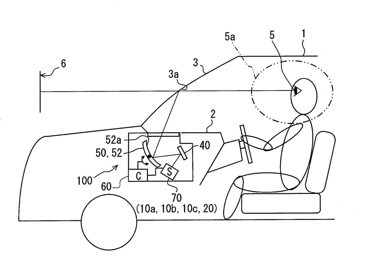
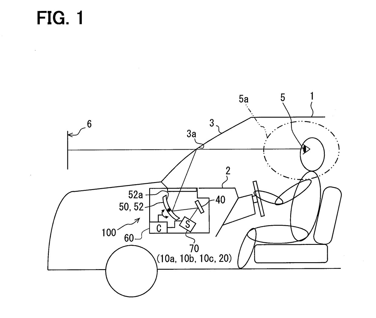
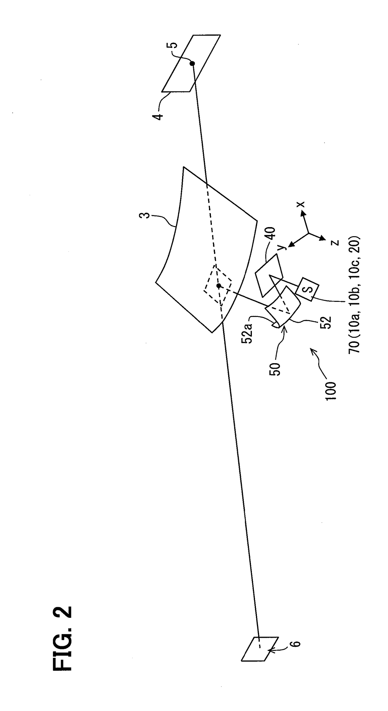
[0033]As illustrated in FIG. 1, a head-up display device 100 according to the first embodiment of the present disclosure is installed in a vehicle 1, which is a type of moving object, and is stored inside an instrument panel 2. The HUD device 100 projects an image onto a windshield 3 which serves as a projection member of the vehicle 1. Accordingly, the HUD device 100 displays the image in a visible region 4 as a virtual image to be visually recognizable by an occupant of the vehicle 1. In other words, the light of the image which is reflected on the windshield 3 reaches an eye point 5 of the occupant inside a vehicle compartment of the vehicle 1, and the occupant senses the light. The occupant is capable of recognizing various types of image which are displayed as a virtual image 6. Examples of various information which is displayed as the virtual image 6 include vehicle state values such as vehicle speed and remaining fuel level, or vehicle information such as road information and...

second embodiment

[0098]As illustrated in FIG. 16, the second embodiment of the present disclosure is a modification example of the first embodiment. Description will be given of the second embodiment, centered on the points which differ from the first embodiment.

[0099]A screen member 240 in the second embodiment is a reflective screen which is mainly formed of a synthetic resin or the like, for example. The screen member 240 includes a diffusion surface 248 which has unevenness in a projection region 240a due to surface textures. In other words, unevenness is provided in the projection region 240a.

[0100]Here, the embossment-like fine unevenness in the diffusion surface 248 is formed unintentionally by a surface etching process, for example; however, the unevenness may be formed by coating or the like of a coating material onto the surface.

[0101]The screen member 240 reflects the light of the image which is diffused through the diffusion surface 248 which has unevenness toward the concave mirror 52 ...

third embodiment

[0104]As illustrated in FIG. 17, the third embodiment of the present disclosure is a modification example of the first embodiment. Description will be given of the third embodiment, centered on the points which differ from the first embodiment.

[0105]A projection optical system 320 of the third embodiment is an optical system which projects a laser light flux onto the screen member 40 in the same manner as in the first embodiment. The projection optical system 320 of the third embodiment includes the three shaping lenses 22a to 22c, the three dichroic filters 24a to 24c, the condenser lens 26, a variable focal point lens 328, and a MEMS scanning mirror 330. Of these, the three shaping lenses 22a to 22c, the three dichroic filters 24a to 24c, and the condenser lens 26 are the same as in the first embodiment. In the third embodiment, the laser light flux which passes through the condenser lens 26 is propagated toward the variable focal point lens 328.

[0106]Here, a controller 360 of the...


PUM


Abstract

An HUD device which is installed on a vehicle and displays an image as a virtual image in a visible region in a manner that is visually recognizable to an occupant by projecting the image onto a windshield includes an oscillator which oscillates a laser light flux, a screen member which has unevenness in a projection region in which the image is formed by projection of the laser light flux, a projection optical system which projects the laser light flux onto the screen member, a magnifying optical system which magnifies the image, projects the image onto the windshield, and guides light of the image to the visible region, and a controller which causes a focal length of the projection optical system to temporally oscillate. Accordingly, an appropriate visible region is secured, luminance inconsistencies in an image which is visually recognized are suppressed, and it becomes easy to secure space.

Description

CROSS-REFERENCE TO RELATED APPLICATION[0001]The present application is based on Japanese Patent Application No. 2014-155482 filed on Jul. 30, 2014, the content of which is incorporated herein by reference.TECHNICAL FIELD[0002]The present disclosure relates to a head-up display device (hereinafter, HUD device will be used as shorthand) which is installed on a moving object and displays an image as a virtual image in a visible region in a manner that is visually recognizable to an occupant by projecting the image onto a projection member.BACKGROUND ART[0003]In the related art, a HUD device which is installed on a moving object and displays an image as a virtual image in a visible region in a manner that is visually recognizable to an occupant by projecting the image onto a projection member is known. A HUD device disclosed in Patent Literature 1 is provided with an oscillator which oscillates a laser light flux, a screen member which has unevenness and forms an image, a projection opt...

Claims


Application Information

Patent Timeline
Patent Type & Authority Applications(United States)
IPC IPC(8): G02B27/01G03B21/20G02B13/16G03B21/00G03B21/62B60K35/00G02B27/48
CPCG02B27/0149G02B2027/013G02B27/0101G03B21/2033G02B27/48G02B27/0179G03B21/008G03B21/62G02B13/16B60K2350/1072B60K2350/2095B60K2350/2052B60K2350/352B60K2350/921G02B2027/011G02B2027/0159G02B2027/0185B60K35/00G02B26/0825G02B26/101G03B21/208B60K2370/155B60K2370/27B60K2370/334B60K2370/52
Inventor NAMBARA, TAKAHIRO
Owner DENSO CORP
Why Eureka
Try Eureka