Medium conveying device and image forming apparatus

a conveying device and medium technology, applied in the direction of instruments, electrographic processes, transportation and packaging, etc., can solve the problems of difficulty in securing a space for providing the lever, and achieve the effect of convenient securing a spa

Active Publication Date: 2015-07-02
OKI DATA CORP
View PDF8 Cites 7 Cited by
  • Summary
  • Abstract
  • Description
  • Claims
  • Application Information

AI Technical Summary

Benefits of technology

[0006]With such a configuration, it becomes easier to secure a space.

Problems solved by technology

In this regard, there is a difficulty in securing a space for providing the lever.

Method used


Image

  • Medium conveying device and image forming apparatus
  • Medium conveying device and image forming apparatus
  • Medium conveying device and image forming apparatus

Examples


embodiment 1

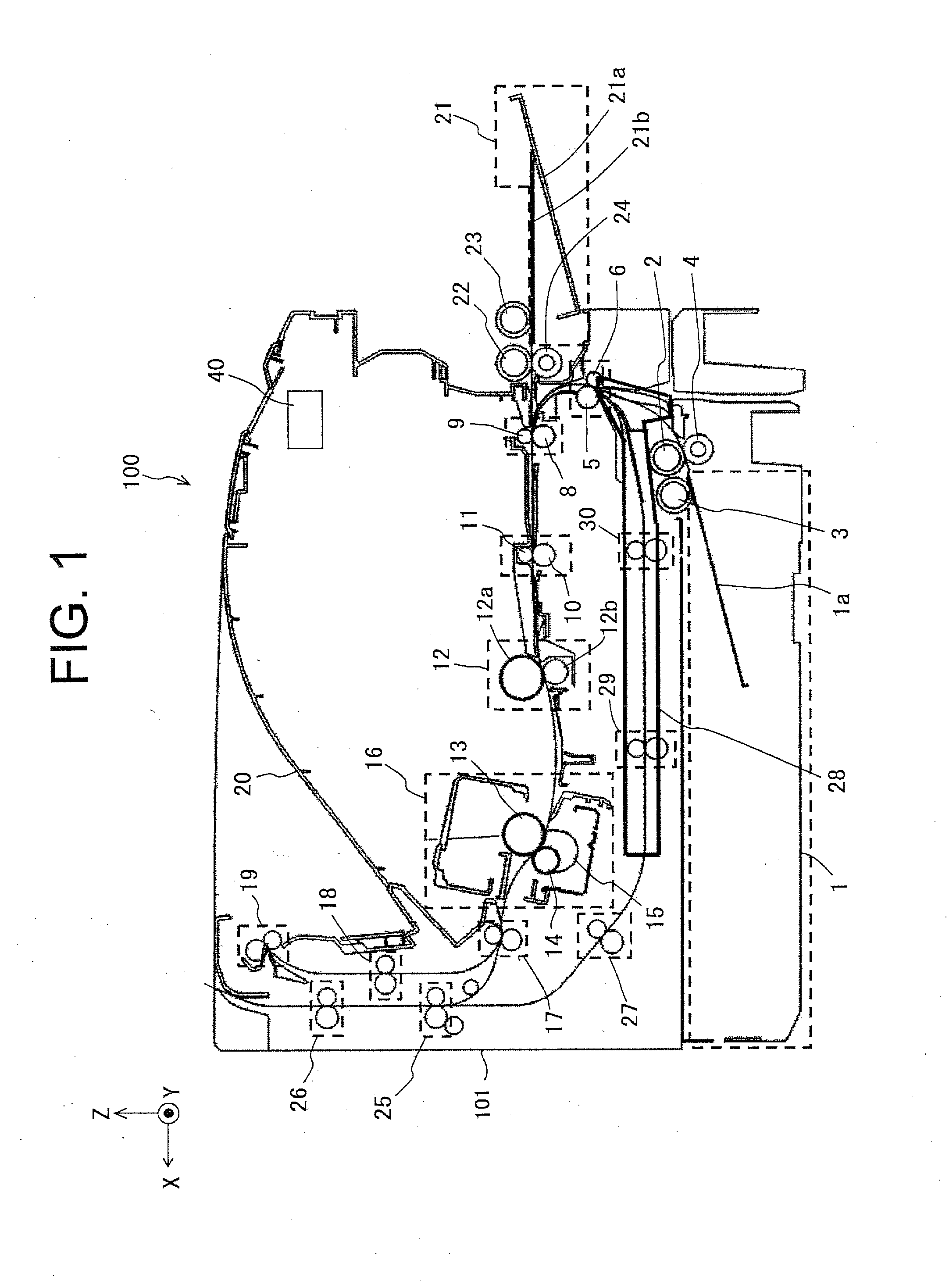
[0033]FIG. 1 is a schematic side view showing a printer 100 including a medium conveying device according to Embodiment 1 of the present invention.

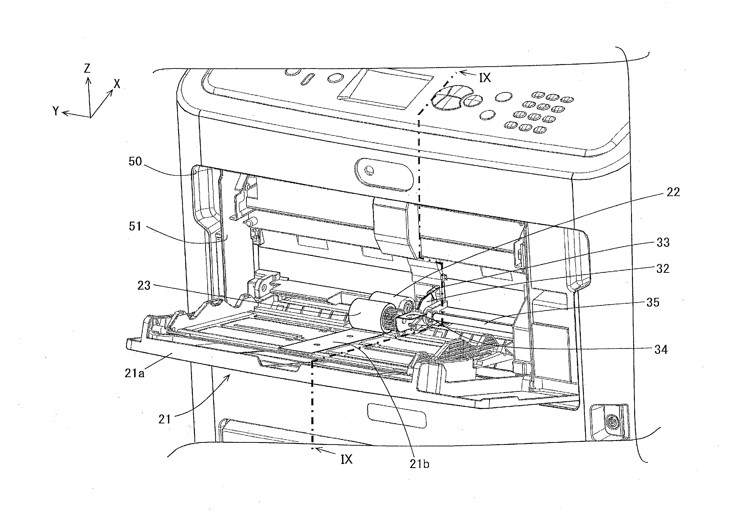
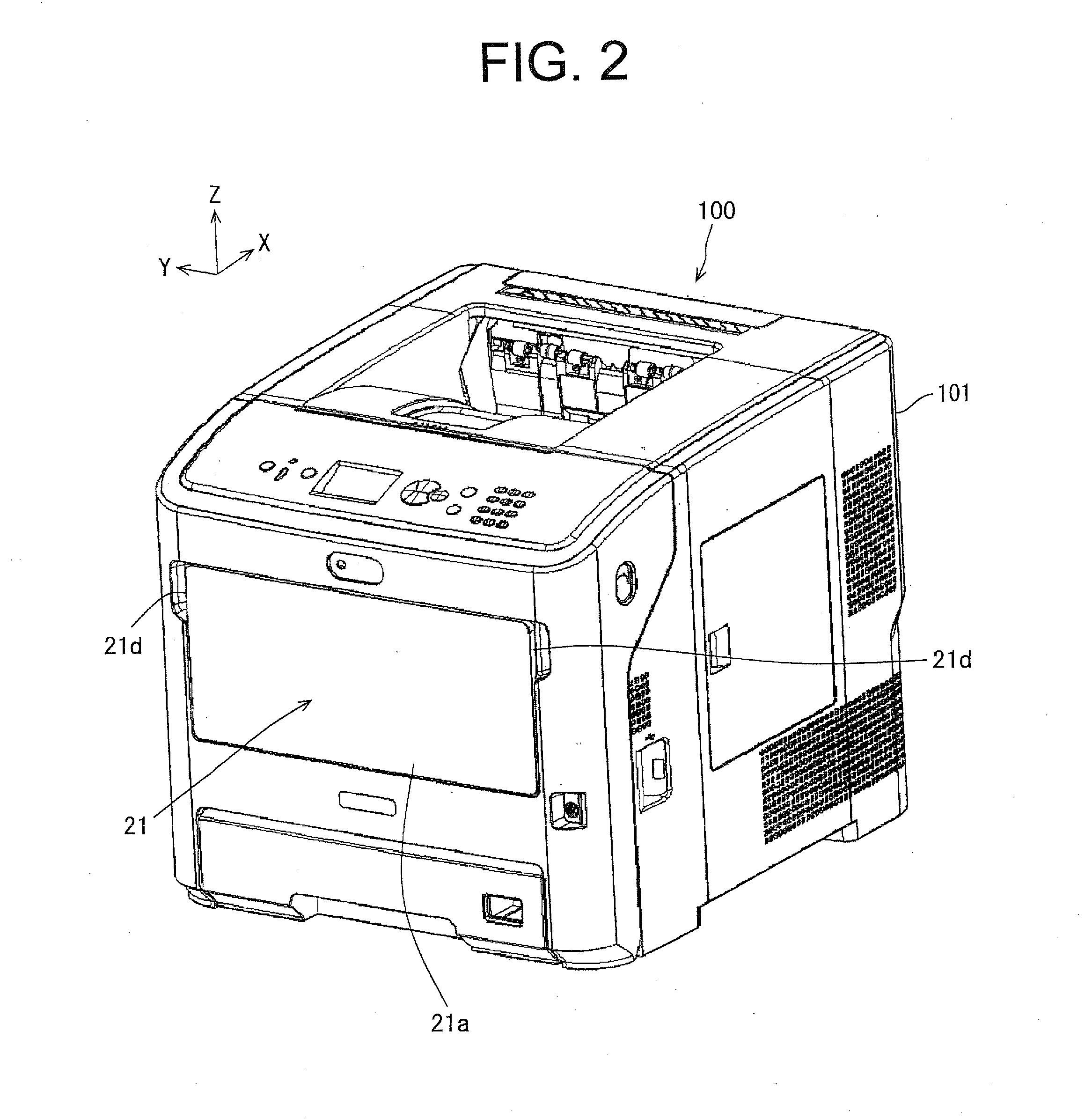
[0034]As shown in FIG. 1, the printer 100 as an image forming apparatus has a function of an electrophotographic printer that forms an image using an LED (Light Emitting Diode). The printer 100 includes a feeding cassette 1, and a manual tray 21 as a manual feeding unit (or a medium placing tray). The manual tray 21 may also be referred to as an MPT (Multi-Purpose Tray). The manual tray 21 includes a manual tray base 21a (described later) and a sheet receiving portion 21b. When the manual tray 21 is to be used, the manual tray 21 is opened with respect to a main body 101 of the printer 100.

[0035]The feeding cassette 1 includes a sheet receiver 1a provided on a sheet ejection side thereof. The sheet receiver 1a is biased upward by a push-up spring (not shown). A feeding sub-roller 3 for feeding a recording sheet is provided so as to face t...

embodiment 2

[0084]FIG. 17 is a sectional view of a part of a printer according to Embodiment 2 taken along the same line as line IX-IX in FIG. 4. FIGS. 19 through 24 are schematic views for illustrating an operation of the manual tray 21 according to Embodiment 2.

[0085]The printer of Embodiment 2 is different from the printer 100 of Embodiment 1 in that the printer of Embodiment 2 includes an MPT slider 133 and a photosensor 136 in instead of the second MPT lever 33 and the mechanical switch 36 of the printer 100 of Embodiment 1. Therefore, elements which are the same as those of the printer 100 (FIG. 1) of Embodiment 1 are assigned with the same reference numerals, and duplicate explanations will be omitted. Description will be focused on a difference between the printer of Embodiment 2 and the printer 100 of Embodiment 1. In this regard, the elements of the printer of Embodiment 2 are the same as those of the printer 100 shown in FIG. 1 except for the second MPT lever 33 and the mechanical sw...


PUM

PropertyMeasurementUnit
displacementaaaaaaaaaa
displacement stateaaaaaaaaaa
forceaaaaaaaaaa

Abstract

A medium conveying device includes a medium placing tray provided on a main body of an image forming apparatus to be openable and closable. The medium placing tray includes a placing portion on which a medium is placed. The medium conveying device includes a first displacement member including a contact portion that contacts the medium placed on the placing portion and a first engaging portion, and a second displacement member including a second engaging portion that engages the first engaging portion. A detecting unit detects a displacement state of the second displacement member. A determination unit determines the presence or absence of the medium on the placing portion based on a detection result of the detection unit. The first engaging portion and the second engaging portion engage and disengages from each other in conjunction with opening and closing operation of the medium placing tray.

Description

BACKGROUND OF THE INVENTION[0001]The present invention relates to a medium conveying device and an image forming apparatus using the medium conveying device.[0002]A general medium conveying device has a medium detection sensor including a lever disposed in a conveying path of a medium. The lever is rotated by the medium, and interrupts a light path of a photosensor. The medium detection sensor detects the medium based on whether the light path is interrupted or not. Such a medium conveying device is disclosed in, for example, Japanese Laid-open Patent Publication No. 2011-93655 (FIG. 4).[0003]In this regard, there is a difficulty in securing a space for providing the lever.SUMMARY OF THE INVENTION[0004]An object of the present disclosure is to make it easier to secure a space.[0005]According to the present disclosure, there is provided a medium conveying device provided on an image forming apparatus. The medium conveying device includes a medium placing tray provided on a main body ...

Claims


Application Information

Patent Timeline
Patent Type & Authority Applications(United States)
IPC IPC(8): B65H3/06B65H7/04B65H3/42B65H7/14G03G15/00B65H1/04
CPCB65H3/0684G03G15/6502B65H7/04B65H3/42B65H7/14B65H1/04G03G2215/00725B65H85/00B65H3/5261B65H5/062B65H9/006B65H2301/33312B65H2402/10B65H2403/53B65H2404/1422B65H2405/324B65H2407/21B65H2553/25B65H2553/61
Inventor KOBAYASHI, YUTA
Owner OKI DATA CORP
Why Eureka
Try Eureka