Switching power supply

Inactive Publication Date: 2008-11-27
RENESAS ELECTRONICS CORP
View PDF6 Cites 28 Cited by
  • Summary
  • Abstract
  • Description
  • Claims
  • Application Information

AI Technical Summary

Benefits of technology

[0022]According to the present invention, an input current can be controlled to a substantially sinusoidal waveform without using a shunt resistor. As well a

Problems solved by technology

However, since a current-detecting resistor (hereinafter, it is called “shunt resistor”) is used in the conventional switching power supply, there are problems that a cost of this shunt resistor and

Method used


Image

  • Switching power supply
  • Switching power supply
  • Switching power supply

Examples


first embodiment

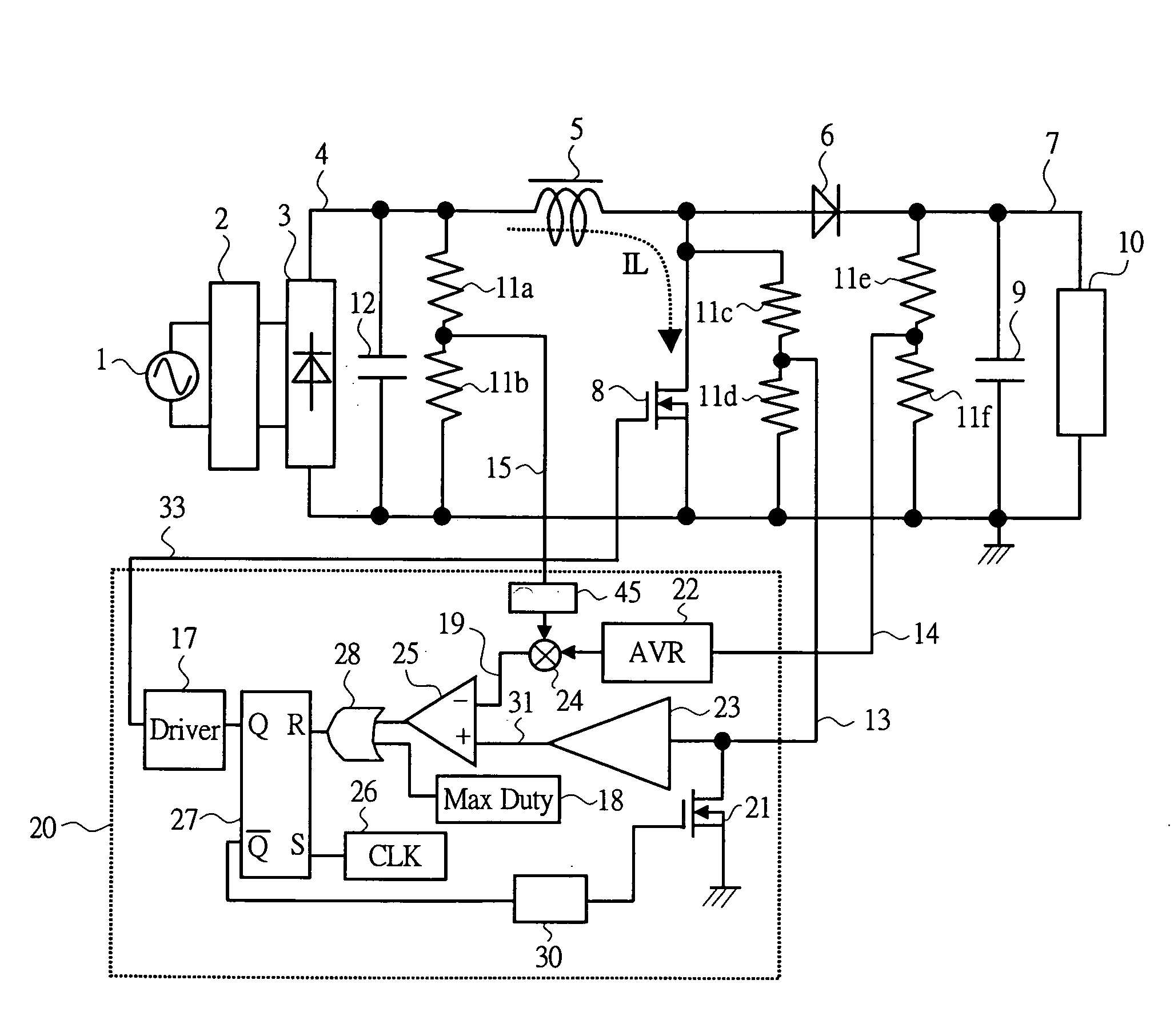
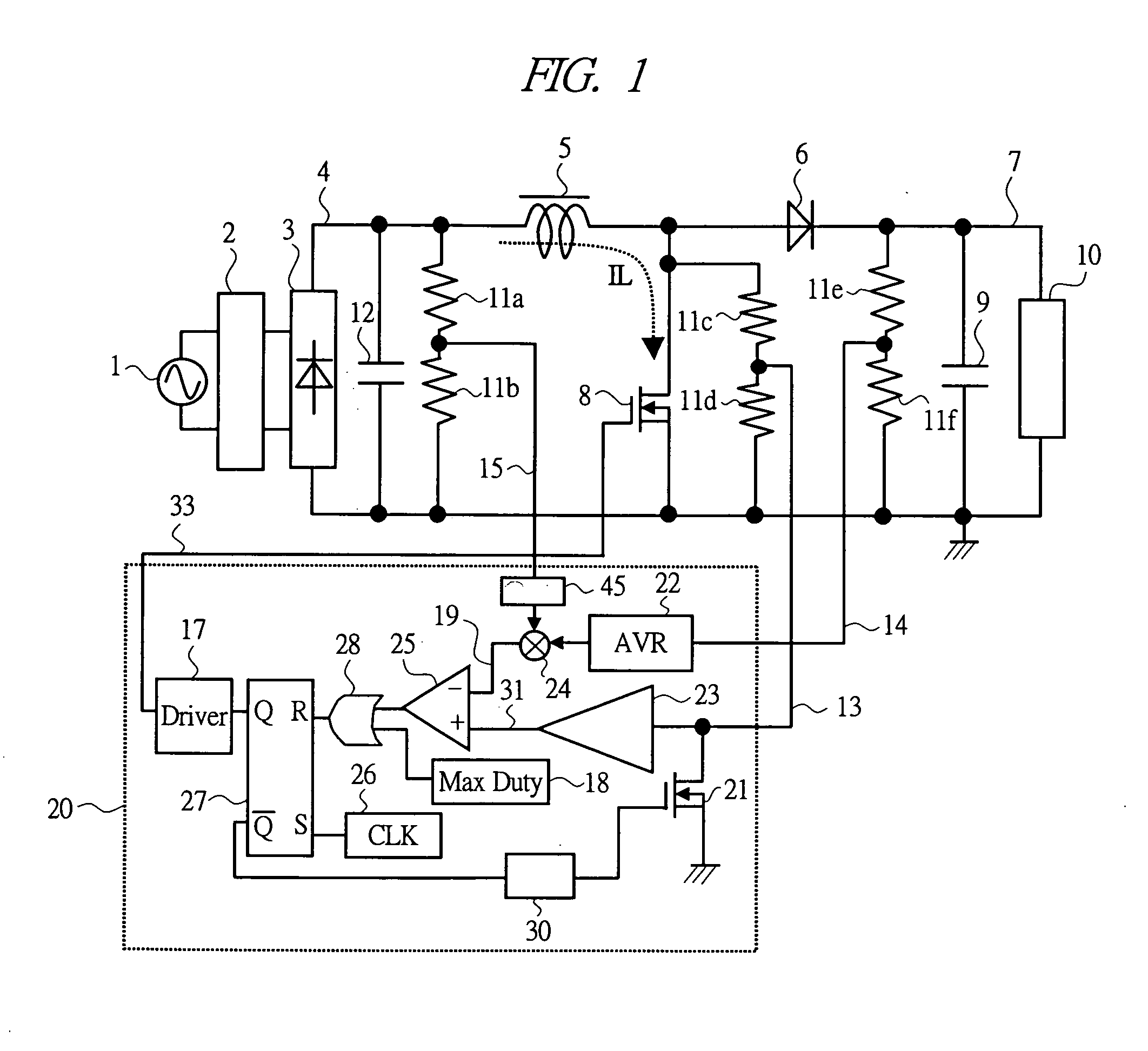
[0041]With reference to FIG. 1, a configuration of a switching power supply according to a first embodiment of the present invention will be described. FIG. 1 is a circuit diagram showing the configuration of the switching power supply according to the first embodiment of the present invention, showing a circuit diagram of a PFC converter as a switching power supply.

[0042]In FIG. 1, the switching power supply comprises: an input filter 2; a rectifier 3; a coil 5; a boost diode 6; a power MOSFET 8; a smoothing capacitor 9; voltage-dividing resistors 11a to 11h, a capacitor 12, and a control circuit 20.

[0043]The control circuit 20 comprises: a driver 17; a maximum Duty circuit 18; a switch 21; an output voltage regulator 22; an amplifier 23; a multiplier 24; a comparator 25; a clock 26; a flip-flop circuit 27; an OR circuit 28; and a delay circuit 30.

[0044]An AC power supply 1 is changed to an input voltage 4 via the input filter 2 and the rectifier 3 which is rectifying means to have...

second embodiment

[0080]Next, with reference to FIG. 1 and FIG. 4, a configuration of a switching power supply according to a second embodiment of the present invention will be described. FIG. 4 is a circuit diagram showing a configuration of a control circuit of the switching power supply according to the second embodiment of the present invention.

[0081]In the switching power supply of the present embodiment, the control circuit 20 of the switching power supply according to the first embodiment shown in FIG. 1 is replaced with the control circuit 20 shown in FIG. 4.

[0082]The control circuit 20 shown in FIG. 4 has a function similar to that of the control circuit 20 of the circuit diagram shown in FIG. 1, and the control circuit 20 in FIG. 4 operates in combination with a main circuit in FIG. 1 by replacing the control circuit in FIG. 1 with the control circuit 20 in FIG. 4. In FIG. 4, parts and blocks having the same functions as in FIG. 1 are applied with the same reference numerals.

[0083]Inside th...

third embodiment

[0103]Next, with reference to FIG. 1 and FIG. 5, a configuration of a switching power supply according to a third embodiment of the present invention will be described. FIG. 5 is a circuit diagram showing a configuration of a control circuit of the switching power supply according to the third embodiment of the present invention.

[0104]In the switching power supply of the present embodiment, the control circuit 20 of the switching power supply of the first embodiment shown in FIG. 1 is replaced with the control circuit 20 shown in FIG. 5.

[0105]The control circuit 20 shown in FIG. 5 has a function similar to the control circuit 20 of the circuit diagram shown in FIG. 1, and the control circuit 20 in FIG. 5 operates in combination with the main circuit in FIG. 1 by replacing the control circuit 20 in FIG. 1 with the control circuit 20 in FIG. 5. In FIG. 5, parts and blocks having the same functions as in FIG. 1 are applied with the same reference numerals.

[0106]In the control circuit 2...


PUM


Abstract

A switching power supply capable of correcting a power factor without using a shunt resistor is provided. The switching power supply includes a rectifier for rectifying an AC power supply, boosting means including a power MOSFET for boosting an output of the rectifier, a smoothing capacitor for smoothing an output of the boosting means, voltage-dividing resistors for detecting a voltage between main terminals of the power MOSFET, a switch for selecting only the voltage by which the power MOSFET is in on-state from voltages detected by the voltage-dividing resistors, an amplifier for amplifying the voltage selected by the switch and outputting the same as a current corresponding value of a current flowing in the power MOSFET, voltage-dividing resistors for detecting the output voltage, and driving means which form a pulse signal based on the current corresponding value and the output voltage for driving the power MOSFET by the pulse signal.

Description

CROSS-REFERENCE TO RELATED APPLICATION[0001]The present application claims priority from Japanese Patent Application No. JP 2007-044845 filed on Feb. 26, 2007, the content of which is hereby incorporated by reference into this application.TECHNICAL FIELD OF THE INVENTION[0002]The present invention relates to a switching power supply. More particularly, the present invention relates to a technique effectively applied to power factor correction of an alternating input current.BACKGROUND OF THE INVENTION[0003]To perform rectification and smoothing to obtain a direct current from an AC power supply, a configuration using a diode bridge and a smoothing capacitor is simplest. Meanwhile, since this configuration results in a rectifier circuit of so-called capacitor input type in which an input current flows only when whose power supply voltage is near the peak, which causes a lowering of power factor or an increase of input harmonic. Since the matter of input harmonic current is regulated ...

Claims


Application Information

Patent Timeline
IPC IPC(8): H02M1/00
CPCH02M1/4225H02M2001/0009Y02B70/126Y02B70/10H02M1/0009
Inventor KANOUDA, AKIHIKOYOKOTA, KENICHI
Owner RENESAS ELECTRONICS CORP
Why Eureka
Try Eureka