Current detection apparatus

a current detection and apparatus technology, applied in the direction of magnetic measurements, instruments, measurement devices, etc., can solve the problems of overdischarge, battery overcharge, and one current detection apparatus b>90/b> alone cannot achieve both battery charge control and battery condition monitor, so as to reduce overall size, reduce manufacturing cost and process, and increase size and cost

Active Publication Date: 2006-10-19
JECO +1
View PDF10 Cites 35 Cited by
  • Summary
  • Abstract
  • Description
  • Claims
  • Application Information

AI Technical Summary

Benefits of technology

[0018] In view of the above-described problem, it is an object of the present invention to provide a current detection apparatus capable of being used for various control purposes related to a detected current without increasing size and cost.
[0019] A current detection apparatus includes a magnetic core having a ring shape with a gap and a center opening portion through which a current path is disposed, and a magnetic sensor including a magnetic sensing element such as a Hall effect element arranged in the gap. When a current flows through the current path, the magnetic core generates magnetic flux therein so that magnetic field is generated in the gap. The magnetic sensor includes a plurality of amplifiers, each of which has a different gain and corresponds to...

Problems solved by technology

If a point where the battery current flows is used as the zero-point for a long time, the battery may be overcharged or overdischarged.
As de...

Method used


Image

  • Current detection apparatus
  • Current detection apparatus
  • Current detection apparatus

Examples


Embodiment Construction

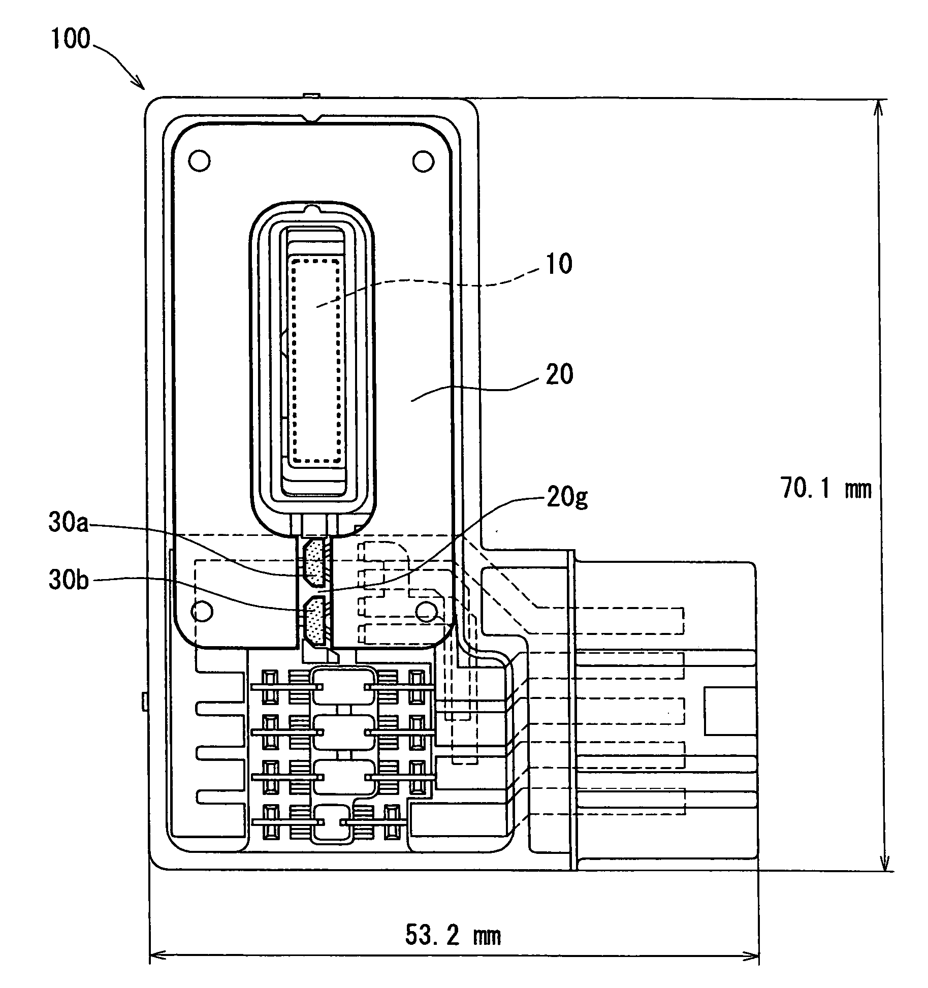
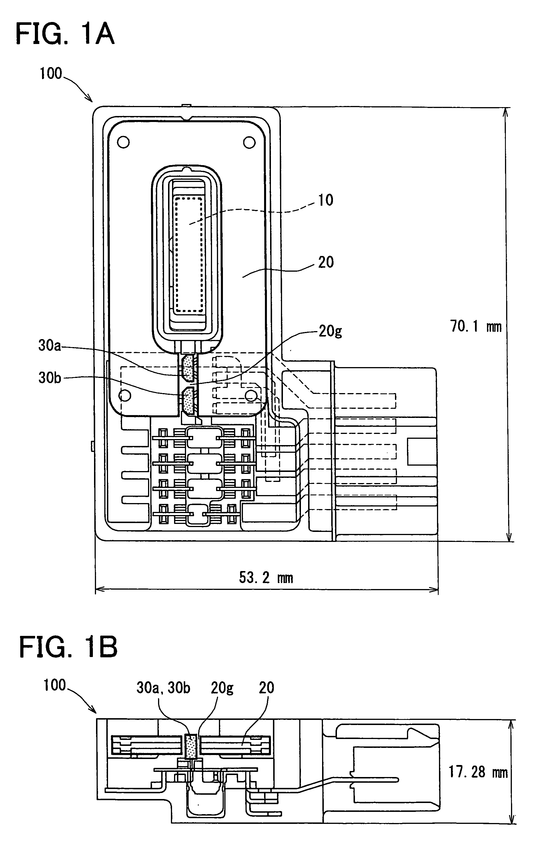
[0031] A current detection apparatus 100 of the first embodiment will now be described with reference to FIGS. 1A to 4B. The current detection apparatus 100 may be, for example, used to measure current of a vehicular battery.

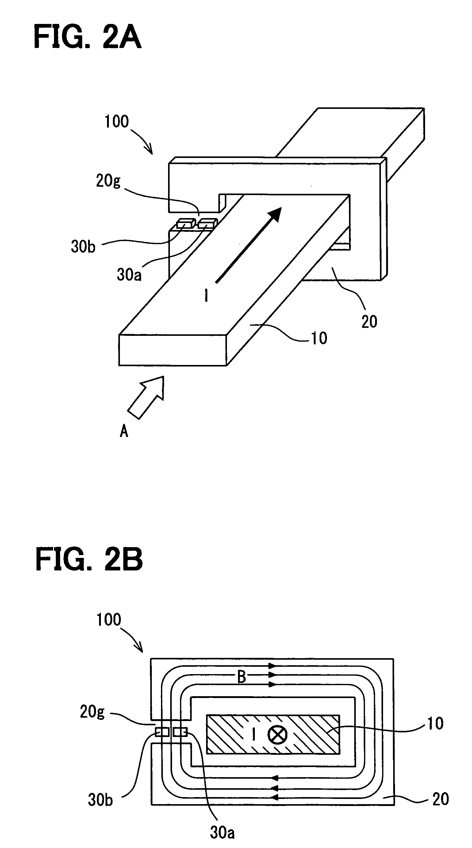
[0032] The current detection apparatus 100 includes a ring-shaped magnetic core 20 having a gap 20g and two magnetic sensors 30a, 30b arranged in the gap 20g. As indicated by a dashed line in FIG. 2A, a busbar 10 is inserted through a center opening of the magnetic core 20 and surrounded by the magnetic core 20. FIG. 2B is a view seen from an arrow A of FIG. 2A. As shown in FIG. 2B, when current I to be measured flows through the busbar 10, magnetic flux B generated by the current I passes through the magnetic core 20. Thus, the magnetic core 20 acts as a magnetic flux path.

[0033] The magnetic core 20 is made of a magnetic material. The magnetic sensors 30a, 30b have different measurement ranges. The magnetic sensors 30a, 30b cover the respective measurement r...


PUM


Abstract

A current detection apparatus includes a magnetic core having a ring shape with a gap and a center opening portion through which a current path is disposed, and a magnetic sensor including a magnetic sensing element such as a Hall effect element arranged in the gap. When a current flows through the current path, the magnetic core generates magnetic flux therein so that magnetic field is generated in the gap. The magnetic sensor outputs different electrical signals, each of which is measured in a different measurement range and corresponds to intensity of the magnetic field in the gap. The current detection apparatus measures the current based on the electrical signals outputted from the magnetic sensor.

Description

CROSS REFERENCE TO RELATED APPLICATION [0001] This application is based on and incorporates herein by reference Japanese Patent Application No. 2005-117566 filed on Apr. 14, 2005. FIELD OF THE INVENTION [0002] The present invention relates to a current detection apparatus for detecting current with a magnetic sensor. BACKGROUND OF THE INVENTION [0003]FIG. 7 is a perspective view showing a current detection apparatus 90 disclosed in JP-A-2002-296305 and used to measure current of an in-vehicle battery. [0004] The current detection apparatus 90 includes a ring-shaped magnetic core 20 having a center opening and a gap 20g and a magnetic sensor 30 arranged in the gap 20g. [0005] As indicated by a dashed line in FIG. 7, a busbar 10 is inserted through the center opening of the magnetic core 20 and surrounded by the magnetic core 20. When current to be measured flows through the busbar 10, magnetic flux is generated in the magnetic core 20. Thus, the magnetic core 20 acts as a magnetic fl...

Claims


Application Information

Patent Timeline
IPC IPC(8): G01R33/07
CPCG01R15/183G01R15/207G01R15/202
Inventor TANIZAWA, YUKIHIKOOOTAKE, SEIICHIROUSAITOU, TAKASHIGEARATANI, MASAHIROTUKAMOTO, TAKESHIISHIHARA, MASATOMIYAHARA, NORIO
Owner JECO
Why Eureka
Try Eureka