Multi-temperature control system and fluid temperature control device applicable to the same system

a control system and fluid temperature technology, applied in the direction of application, lighting and heating apparatus, etc., can solve the problems of inability to accurately control the temperature of the portion of all the process chambers at the same level, difficulty in accurately controlling the temperature, and inability to accurately control the temperature, etc., to achieve low light, low light absorption, and relatively small temperature non-uniformity

Inactive Publication Date: 2000-11-14
KOMATSU LTD
View PDF2 Cites 21 Cited by
  • Summary
  • Abstract
  • Description
  • Claims
  • Application Information

AI Technical Summary

Benefits of technology

In the fluid temperature control device according to the present invention, the fluid flowing through the inner space can be heated by radiation heat emitted from the lamp. Since the radiation heat is utilized, the temperature non-uniformity is relatively small. Further, since the fins are arranged in the inner space, even if the fluid is a substance having an extremely low light absorbability, the radiation heat can be rece...

Problems solved by technology

In addition, it is also impossible to control all the temperatures of the portions of all the process chambers at the same level accurately.
In this method, however, since the control construction may be considerably complicated, and further since the fluid flow rate control may be interfered with each other between the process chambers, it is difficult to control the temperature accurately.
As a result, the fluid circulation pipes are inevitably lengthened, and further the quantity of working fluid to be used increases.
However, since these non-active working fluids are considerably expensive, it is not preferable to use a large quantity of these fluid.
However, since the low-cost working fluid produces ions by the influence of plasma generated within the process chamber and thereby the process chamber is easily corroded, a deionizing instrument of large size and of high cost is additionally required.
Further, in the prior art temperature control system, since the fluid circulation pipes are relatively long, the thermal loss is large in the circulation pipes.
As a result, a relatively large heat capacity is necessary for each temperature control mach...

Method used


Image

  • Multi-temperature control system and fluid temperature control device applicable to the same system
  • Multi-temperature control system and fluid temperature control device applicable to the same system
  • Multi-temperature control system and fluid temperature control device applicable to the same system

Examples


Embodiment Construction

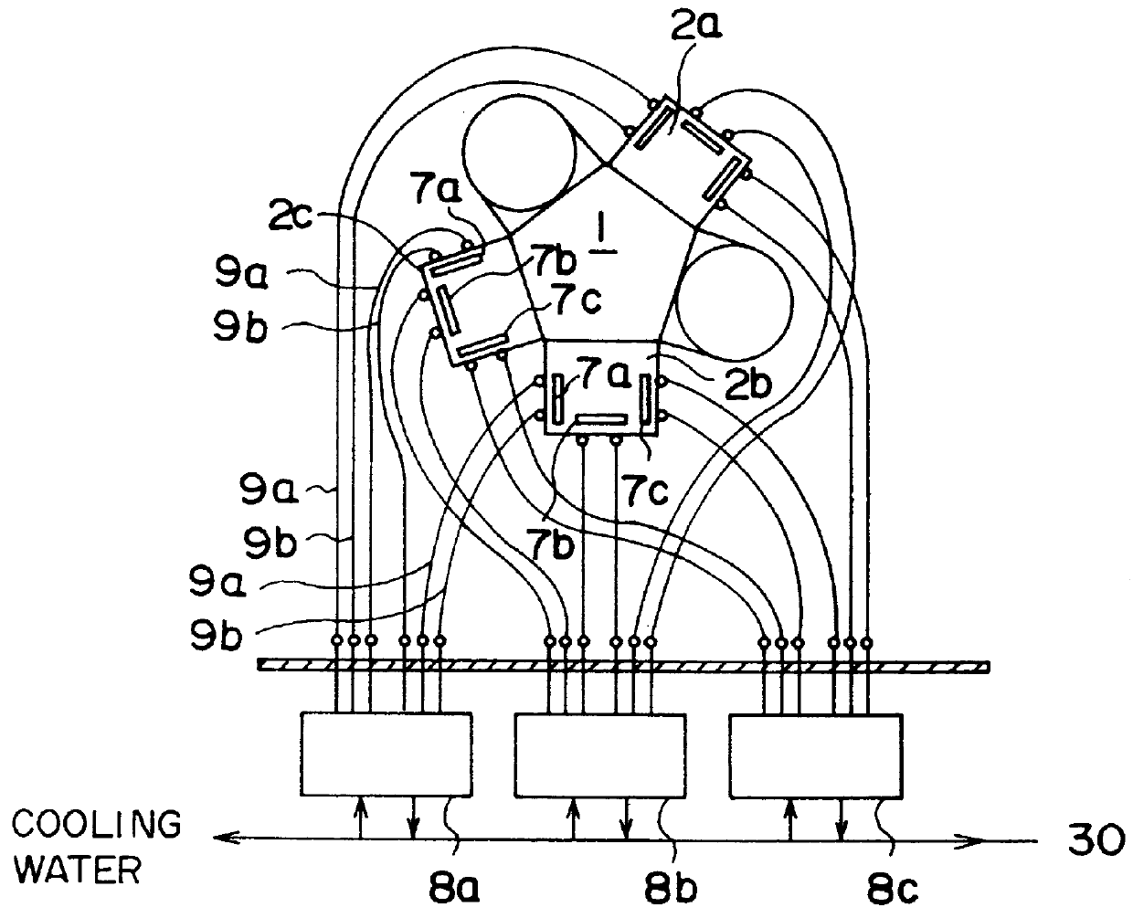
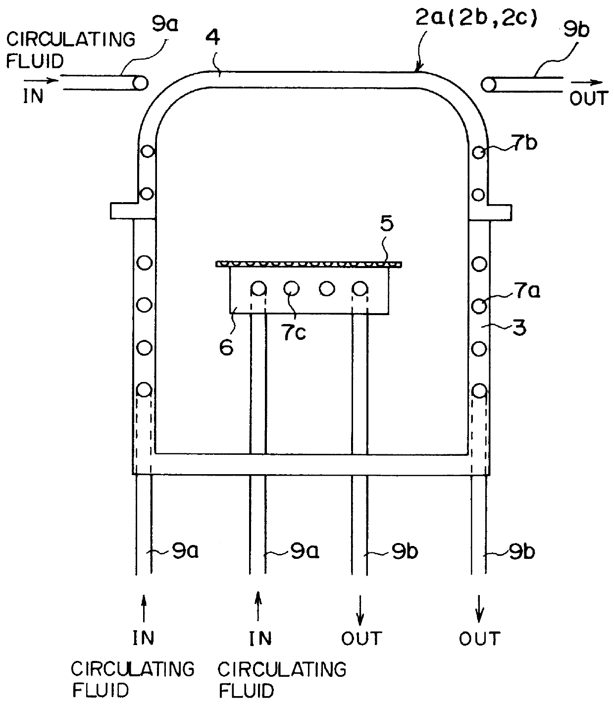
FIG. 4 shows an entire construction of an embodiment of the multi-temperature control system according to the present invention, which is applied to the semiconductor processing apparatus. Here, since the semiconductor processing apparatus is substantially the same as the prior art apparatus shown in FIGS. 1 and 2, the same reference numerals have been retained for similar elements or parts having the same functions as with the case of the prior art apparatus, without repeating the similar description thereof.

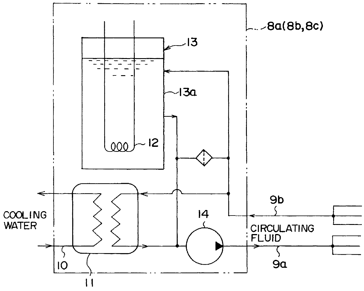
As shown in FIG. 4, a set of three small-sized temperature control machines 15a, 15b and 15c are provided for each of the three process chambers 2a, 2b and 2c of the semiconductor processing apparatus, respectively. In other words, one set of three temperature control machines 15a, 15b and 15c are provided for the first process chamber 2a. In the same way, another set of three temperature control machines 15a, 15b and 15c are provided for the second process chamber 2aand a furt...


PUM

PropertyMeasurementUnit
Temperatureaaaaaaaaaa
Transparencyaaaaaaaaaa
Lightaaaaaaaaaa

Abstract

A fluid temperature control device is improved to be simpler in structure, less in fluid temperature non-uniformity, and able to heat a fluid having a small light absorbability. The fluid temperature control device has a cylindrical inner vessel (20), a cylindrical outer vessel (22) surrounding the inner vessel (20), and a heating lamp (25) inserted into the inner vessel (20). Metal fins (28a) and (28b) are provided on the inner and outer circumferential surfaces of the inner vessel (20). A working fluid is passed through the inner space (21) between the inner vessel (20) and the heating lamp (25) and a cooling liquid is passed through the outer space (23) between the inner vessel (20) and the outer vessel (22). Infrared rays from the heating lamp (25) heat the working fluid, and the cooling liquid cools the working fluid. This device is applicable to, for instance, temperature control of plural process chambers of semiconductor processing apparatus. A plurality of the temperature control devices are arranged in the vicinity of the semiconductor processing apparatus. Each of the devices is assigned to each of plural portions of the process chambers and provides the temperature-controlled fluid exclusively to each portion.

Description

The present invention relates to a multi-temperature control system for controlling temperatures at a plurality of places using circulation of a working fluid, and also relates to a fluid temperature control device which is applicable to the same system.The multi-temperature control system according to the present invention can be preferably used, for instance, to control temperatures of various portions in a plurality of process chambers (reaction processing chambers) of a semiconductor processing apparatus; without being limited only thereto, however, this system can be applied to the other various reaction processing apparatus.The fluid temperature control device according to the present invention is applicable not only to the multi-temperature control system of this invention, but also to the other various type temperature control systems.The conventional semiconductor processing apparatus is constructed as shown in FIG. 1, for instance. In more detail, a plurality of process ch...

Claims


Application Information

Patent Timeline
IPC IPC(8): F24H1/12F24H1/14C23C14/34F24H1/10
CPCF24H1/142F24H2250/14F28D7/00
Inventor KADOTANI, KANICHI
Owner KOMATSU LTD
Why Eureka
Try Eureka