Sensor with laser welded cover

a technology of laser welding and sensors, applied in the field of sensors, can solve problems such as short circuits or destruction of sensor elements or connections, and errors in measurements,

Active Publication Date: 2016-08-30
ASM AUTOMATION SENSORIK MESSTECHN GMBH
View PDF28 Cites 1 Cited by
  • Summary
  • Abstract
  • Description
  • Claims
  • Application Information

AI Technical Summary

Benefits of technology

[0012]Since the cover is welded to the housing through a laser the temperature induction into the housing is so small that the sensor element which has to be mounted previously therein is not damaged and the circuit board is not damaged either on which the sensor element, typically a chip, is placed and the housing and the cover are not subject to a temperature induced warp.
[0014]Both components are preferably made from metal, in particular the same metal, preferably a non-magnetizable metal so that the magnetic field of an encoder magnet positioned outside of the housing can permeate the cover without problems towards the sensor element arranged in the housing. For this purpose and in order to make the housing stable, the cover is much thinner than the wall thickness of the surrounding pot shaped housing and thus in particular at the most 1 / 10 better at the most 1 / 20 of the maximum wall thickness of the pot shaped housing, in absolute terms at the most 1.5 mm, better at the most 1.0 mm, better 0.5 mm.
[0017]Thus, the housing is tight after the cover is welded on, besides the cable outlet as a single additional opening, wherein the cable outlet is required for running out the signals when there is no wireless connection from the interior of the housing to the outside. The cable outlet, however, can be carefully sealed or glued in and reduces the probability of leaks compared to a larger number of locations to be sealed.
[0019]This intermediary pot can be made from metal or also from a temperature resistant plastic material which minimizes the heat conduction from the welding location to the sensor element even better.
[0022]For simple and precise production the housing is preferably produced as a turned component, the cover, however, is produced as a stamped component.

Problems solved by technology

As soon as the housing develops a leak, humidity penetrates towards the sensor element and causes erroneous measurements, short circuits or a destruction of the sensor element or of its connections.

Method used


Image

  • Sensor with laser welded cover
  • Sensor with laser welded cover
  • Sensor with laser welded cover

Examples


Embodiment Construction

a) Technical Object

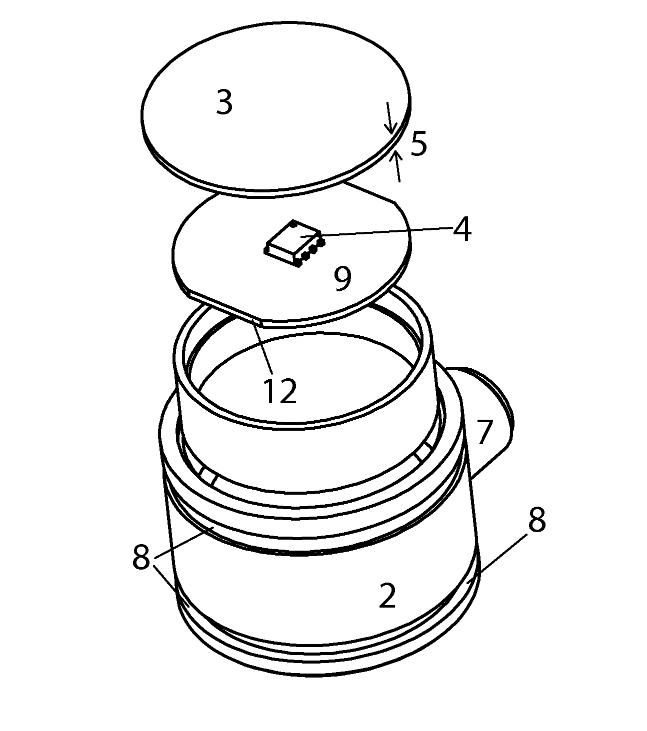
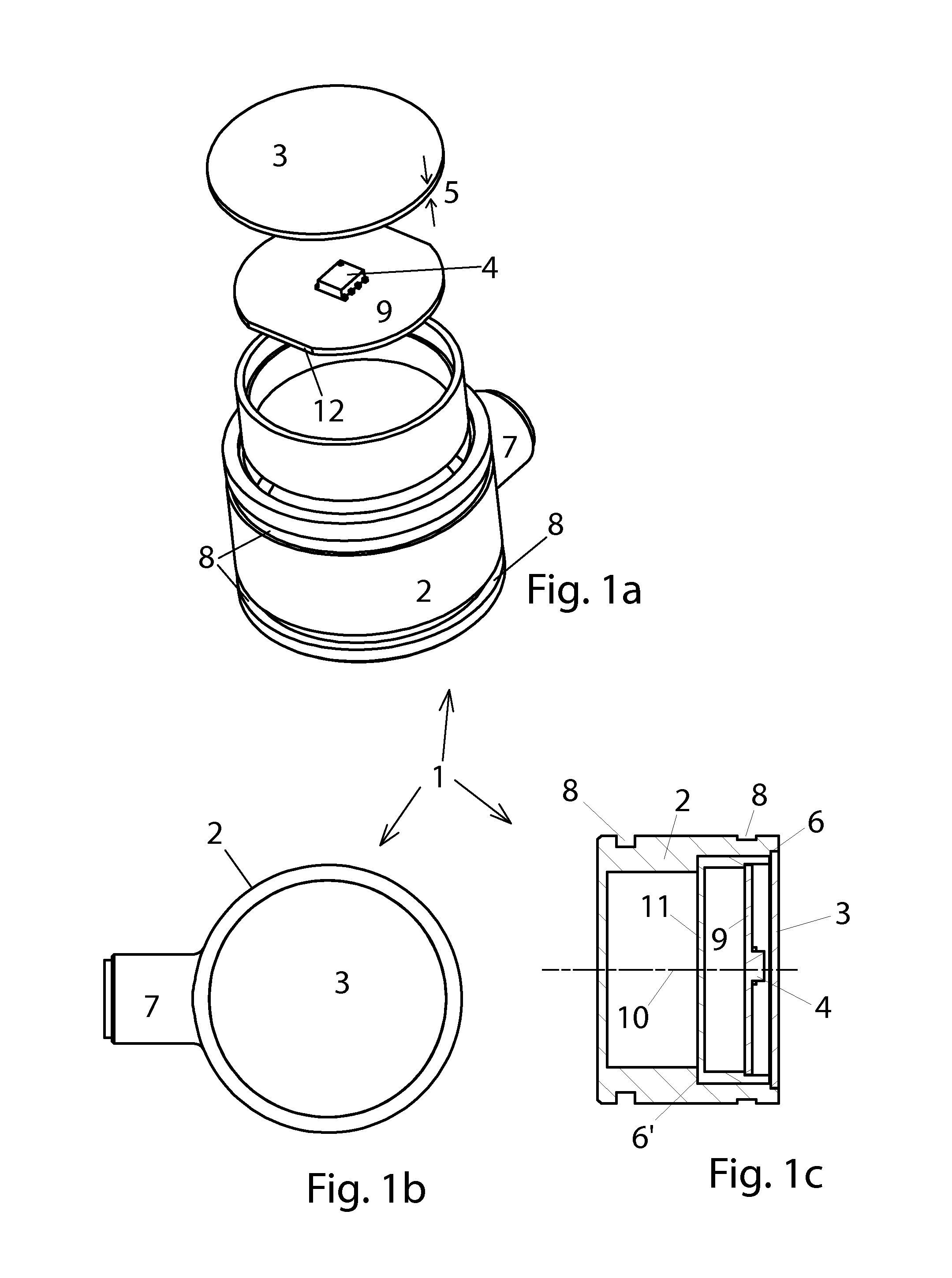
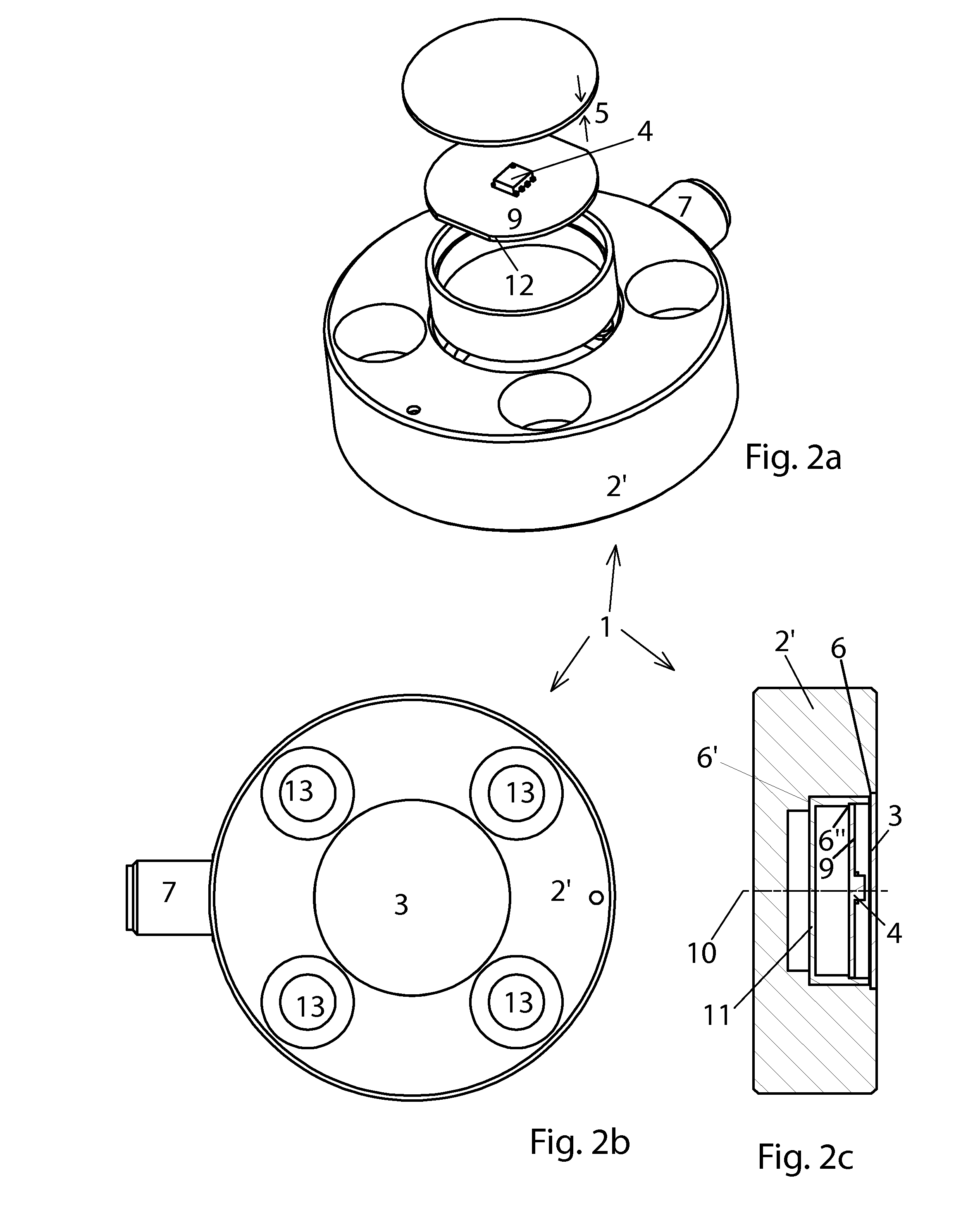
[0010]Thus it is the object of the invention to provide a housing for a magnetic field sensitive sensor which is safely sealed in an optimum manner for a long time.

b) Solution

[0011]The object is achieved through the features of claim 1. Advantageous embodiments can be derived from the dependent claims.

[0012]Since the cover is welded to the housing through a laser the temperature induction into the housing is so small that the sensor element which has to be mounted previously therein is not damaged and the circuit board is not damaged either on which the sensor element, typically a chip, is placed and the housing and the cover are not subject to a temperature induced warp.

[0013]In order to be able to automate the welding the best way possible and in order to be able to assure in particular an even velocity of the laser along the weld gap which avoids punctiform temperature peaks, the pot shaped housing is preferably configured rotation symmetrical and the cover is ...


PUM


Abstract

In order to configure a housing of a sensor, in particular of an angle sensor, long term leak tight in the best way possible a cover is not glued into the pot shaped housing or screwed in and sealed, but welded in the housing through a laser. In spite of the sensor chip already being in the housing, the heat induction is so small that the sensor chip is not damaged even though the sensor chip is very small.

Description

I. FIELD OF THE INVENTION[0001]The invention relates to sensors.II. BACKGROUND OF THE INVENTION[0002]Sensors, in particular angle sensors determine an actual position of a component to be monitored, e.g. an angle position and emit this in the form of an electrical signal for further processing.[0003]In magnetic field sensitive sensors a sensor element typically includes an integrated electronic circuit in the form of a chip which can measure the pole orientation of a magnetic field, wherein the sensor element is disposed within an area influenced by the magnetic field.[0004]Accordingly, the sensor element is disposed in a tight housing from which only a cable is run out for putting out signals, whereas a magnet configured as an encoder element is arranged on a component to be detected, e.g. a rotating shaft outside of the housing and opposite to the sensor element.[0005]Since applications of this type often take place under rough environmental conditions like high pressure, high tem...

Claims


Application Information

Patent Timeline
Patent Type & Authority Patents(United States)
IPC IPC(8): G01P1/02G01D11/24
CPCG01D11/245G01P1/026
Inventor STEINICH, KLAUS MANFRED
Owner ASM AUTOMATION SENSORIK MESSTECHN GMBH
Why Eureka
Try Eureka