Solder bath and method of heating solder contained in the solder bath

a technology of solder bath and solder bath, which is applied in the direction of soldering apparatus, lighting and heating apparatus, and immersion heating arrangements, etc., can solve the problems of solder bridge, soldering defect, and soldering bridge, and achieve easy partial variation in temperature.

Inactive Publication Date: 2012-09-06
SENJU METAL IND CO LTD
View PDF3 Cites 0 Cited by
  • Summary
  • Abstract
  • Description
  • Claims
  • Application Information

AI Technical Summary

Benefits of technology

[0009]In the disclosures in Japanese Patent Application Publication NOS. H06-41965, H05-18756, H03-254362, S52-127449 and 2005-7405, in each of which the heater heats the solder bath main body with the heater being fixed to an outer surface of the solder bath main body, however, a heater-connected part of the outer surface of the solder bath main body is strongly heated to rise in its temperature. A part thereof which is away from a heater, however, rises in little temperature so that temperature in the solder bath main body varies widely, thereby causing the solder contained in the solder bath main body to easily vary in temperature partially. When the temperature of the solder varies, the temperature of the solder flowing out of a discharge nozzle installed inside the solder bath main body also easily varies, thereby resulting in defective soldering with faculty.
[0012]Further, in each of the disclosures in Japanese Patent Application Publication NOS. H06-41965, H05-18756, H03-254362, S52-127449 and 2005-7405, a heater-connected part of the outer surface of the solder bath main body is locally heated to generate any thermal expansions partially. This causes to be shortened the life of the solder bath main body. Any heat for heating the solder bath main body diffuses the outer surface of the solder bath main body into the air, so that the thermal efficiency thereof may deteriorate.
[0019]According to the embodiments of the invention, it is possible to heat the solder contained in the solder bath main body as evenly as possible and to melt the solder. This can restrain any soldering defects such as a solder bridge and a lack of solder from occurring. This also prevents the life of the solder bath main body from being shortened. According to the embodiments of the invention, the porous heat insulator prevents any heat for heating the solder from escaping from the outer surface of the solder bath main body into the air, so that the thermal efficiency thereof may be improved.

Problems solved by technology

When the temperature of the solder varies, the temperature of the solder flowing out of a discharge nozzle installed inside the solder bath main body also easily varies, thereby resulting in defective soldering with faculty.
Thus, in the lead-free solder, any soldering defects such as a solder bridge and a lack of solder may occur if the temperature of the solder varies even slightly by means of heating by the heater.
This causes to be shortened the life of the solder bath main body.
Any heat for heating the solder bath main body diffuses the outer surface of the solder bath main body into the air, so that the thermal efficiency thereof may deteriorate.

Method used


Image

  • Solder bath and method of heating solder contained in the solder bath
  • Solder bath and method of heating solder contained in the solder bath
  • Solder bath and method of heating solder contained in the solder bath

Examples


Embodiment Construction

[0028]The inventors have found that it is possible to heat the solder contained in the solder bath main body as evenly as possible and to melt the solder by followings:

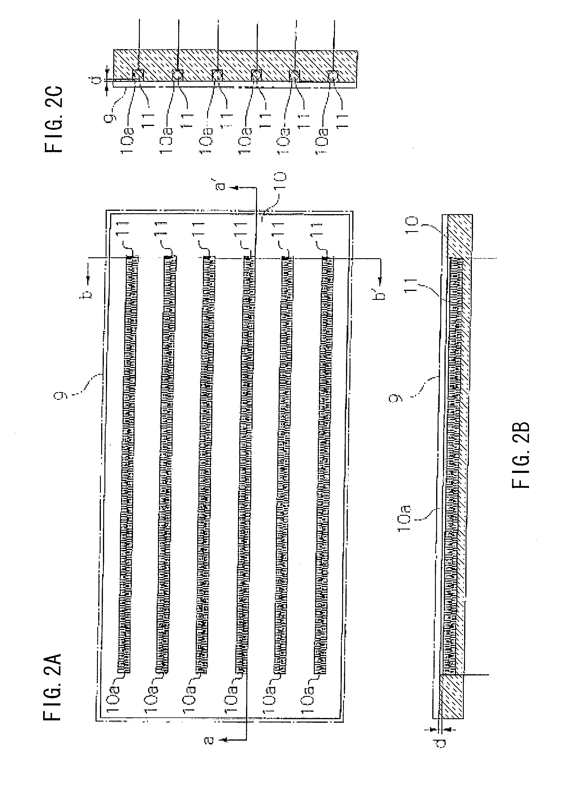
[0029](a) A heating member does not directly heat the solder bath main body but heats the thermal diffusion member made of stainless steel and mounted on the outer surfaces of the bottom and sides of the solder bath main body and the thermal diffusion member heats the solder bath main body through thermal diffusion from the thermal diffusion member; and

[0030](b) A heating resistive element, which is buried in the porous heat insulator that is mounted on and attached to the thermal diffusion member and which is away from the thermal diffusion member heats the thermal diffusion member. They then invent embodiments of the present invention.

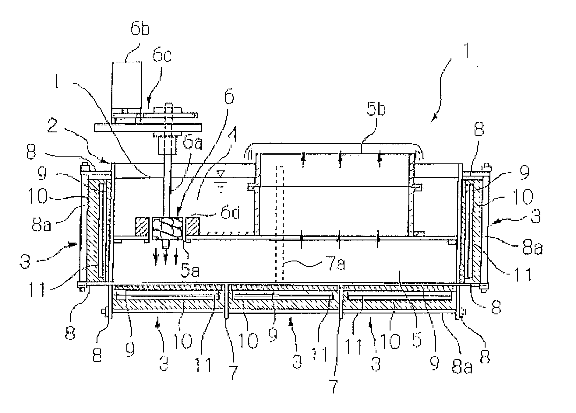
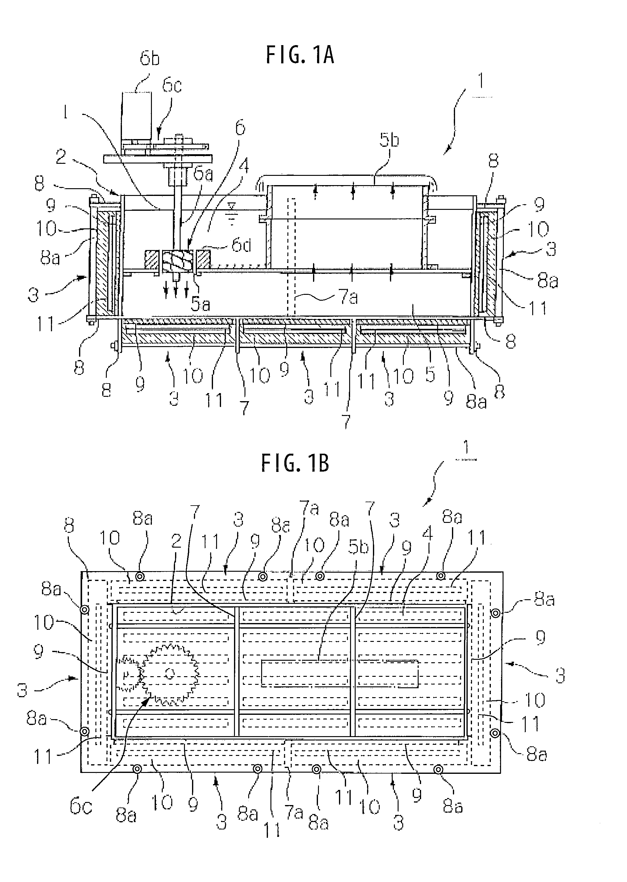
[0031]The following will describe the embodiments of the present invention with reference to the drawings. FIGS. 1A and 1B show a configuration of an embodiment of a solder bath 1 acco...


PUM

PropertyMeasurementUnit
temperatureaaaaaaaaaa

Abstract

A solder bath comprises a solder bath main body containing lead-free solder. A heating member heats the solder and is mounted on outer surfaces of a bottom and sides of the solder bath main body. The heating member contains a thermal diffusion member that is made of stainless steel, a porous heat insulator that is mounted on and attached to the thermal diffusion member, and a heating element that is buried in the porous heat insulator. The heating element is also away from the thermal diffusion member. The thermal diffusion member is heated by heat of the heating element to heat the solder bath main body evenly through thermal diffusion from the thermal diffusion member up to a constant range of temperature and the solder contained in the solder bath is heated evenly to a constant range of temperature.

Description

CROSS-REFERENCE TO RELATED APPLICATIONS[0001]This application is a divisional of co-pending U.S. patent application Ser. No. 12 / 646,819 filed Dec. 23, 2009 and contains subject matter related to Japanese Patent Application JP 2008-335448 filed in the Japanese Patent Office on Dec. 27, 2008, the entire contents of which being incorporated herein by reference.BACKGROUND OF THE INVENTION[0002]1. Field of the Invention[0003]The present invention relates to a solder bath and a method of heating solder contained in the solder bath.[0004]2. Description of Related Art[0005]It is well known that a solder bath main body of a solder bath is heated in order to perform temperature control strictly on solder when soldering, for example, a printed circuit board using the solder bath.[0006]For example, Japanese Patent Application Publication NO. 2003-136233 has disclosed an automatic soldering apparatus. In the automatic soldering apparatus, solder contained in the solder bath is heated using a she...

Claims


Application Information

Patent Timeline
Patent Type & Authority Applications(United States)
IPC IPC(8): F24H9/00
CPCB23K3/0646B23K1/085
Inventor SATO, ISSAKUTAKAGUCHI, AKIRA
Owner SENJU METAL IND CO LTD
Why Eureka
Try Eureka