Cooling structure for a work vehicle

a technology for working vehicles and cooling structures, applied in indirect heat exchangers, machines/engines, light and heating apparatus, etc., can solve the problems of large working vehicle size and cost, and achieve the effect of not increasing the size and cost of the working vehicl

Active Publication Date: 2009-07-14
KUBOTA CORP
View PDF17 Cites 20 Cited by
  • Summary
  • Abstract
  • Description
  • Claims
  • Application Information

AI Technical Summary

Benefits of technology

[0004]The object of this invention is to provide a cooling structure for cooling oil without increasing the size and cost of a working vehicle.
[0007]Therefore, the oil can be cooled without increasing the size and cost of the working vehicle.

Problems solved by technology

Thus, the working vehicle tends to become large and costly.

Method used


Image

  • Cooling structure for a work vehicle
  • Cooling structure for a work vehicle
  • Cooling structure for a work vehicle

Examples


Embodiment Construction

[0020]An embodiment in which this invention is applied to a riding type mowing machine which is one example of working vehicles will be described hereinafter.

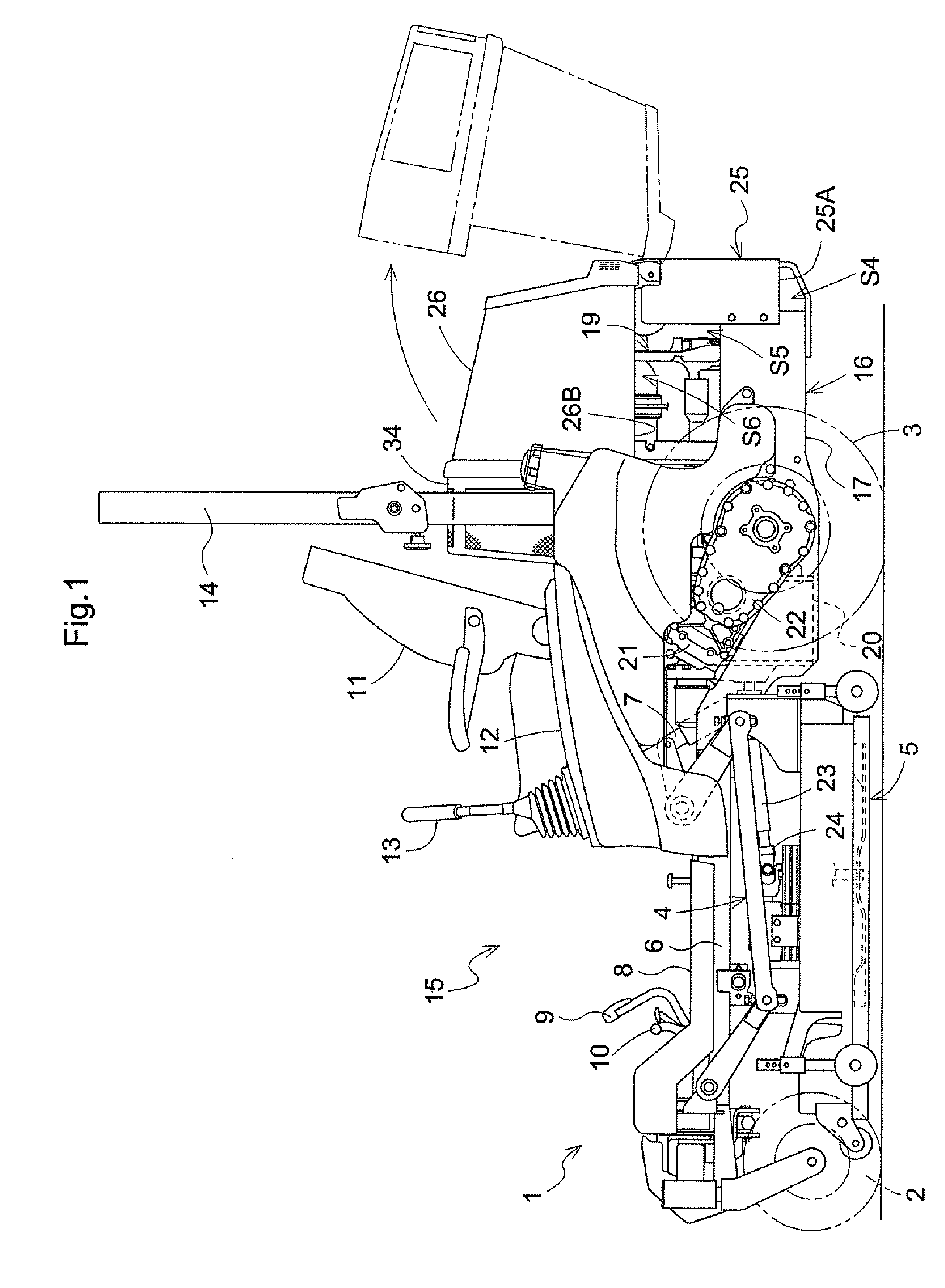
[0021]FIG. 1 shows a side elevation of the riding type mowing machine. As shown in FIG. 1, the riding type mowing machine in this embodiment is constructed the mid-mount type having a mower 5 vertically movably attached through a link mechanism 4 to a vehicle body 1 between a pair of right and left front wheels 2 and a pair of right and left rear wheels 3.

[0022]The vehicle body 1 includes a front frame 6 formed of square pipe or the like and disposed in a front part thereof. The front frame 6 supports the link mechanism 4, and has right and left front wheels 2 arranged at right and left ends of a front end thereof to be dirigible about vertical axes. The link mechanism 4 can raise and lower the mower 5 in parallel by operation of a single-acting hydraulic cylinder 7.

[0023]The front frame 6 has a boarding step 8 formed of sheet ...


PUM


Abstract

A cooling structure for a working vehicle with a transmission disposed rearwardly and downwardly of a driver's seat and having a hydrostatic transmission, and an air-cooled engine disposed rearwardly of the transmission. The cooling structure comprising a fan for cooling the engine and a fan for cooling the transmission mounted on a rotary shaft operatively connecting the transmission with an output shaft of the air-cooled engine, the fans being configured such that air flows generated by the fans move from adjacent the transmission toward the engine; an oil cooler for cooling fluid supplied to the hydrostatic transmission, the oil cooler being disposed between the fan for cooling the engine and the fan for cooling the transmission, and disposed to face each of the fans; and an air guiding plate disposed at a position higher than the oil cooler for guiding air to regions of the fans.

Description

BACKGROUND OF THE INVENTION[0001]This invention relates to a cooling structure for a working vehicle having an oil cooler.[0002]A known cooling structure for a working vehicle having a water-cooled engine includes a cooling fan driven by the engine for cooling a radiator. Cooling air flows generated by the cooling fan are supplied to the radiator and an oil cooler opposed to the radiator to cool oil (see JP 2007-9825, for example).[0003]In the above construction, the working vehicle has the water-cooled engine requiring many accessories such as the radiator and a water pump. Thus, the working vehicle tends to become large and costly.SUMMARY OF THE INVENTION[0004]The object of this invention is to provide a cooling structure for cooling oil without increasing the size and cost of a working vehicle.[0005]A cooling structure for a working vehicle, according to this invention, with a transmission disposed rearwardly and downwardly of a driver's seat and having a hydrostatic transmission...

Claims


Application Information

Patent Timeline
Patent Type & Authority Patents(United States)
IPC IPC(8): F01P5/02F28D15/00
CPCF01P5/06F01P2060/045F01P7/044
Inventor YAMADA, MASAHIROTOGOSHI, YOSHIKAZUMINOURA, AKIRAUEDA, YOSHIHIROESAKI, YOSHIYUKISATOU, EIJIKOMORIDA, TAKESHI
Owner KUBOTA CORP
Why Eureka
Try Eureka