Headlamp assembly

a headlamp and assembly technology, applied in the field of headlamp assemblies, can solve the problems of short life, reduced light emission efficiency, intrinsic drawbacks of light emitting diodes, etc., and achieve the effects of increasing the radiating capability of the headlamp assembly, increasing the flow speed of air, and different heat capacity

Inactive Publication Date: 2011-10-20
NIPPON SOKEN +1
View PDF2 Cites 20 Cited by
  • Summary
  • Abstract
  • Description
  • Claims
  • Application Information

AI Technical Summary

Benefits of technology

[0011]It is an object of the present invention to provide a headlamp assembly for vehicles with increased radiating capability without increasing the size and electric power consumption of the headlamp assembly.
[0023]In the headlamp assembly for vehicles according to the present invention, because the upper part and the bottom part of each of the radiating fins have a different heat capacity, the upper part and the bottom part of the radiating fin have a different temperature when the light source works. Such a structure of the radiating fins increases the flow speed of air in the gap between the adjacent radiating fins without increasing the entire size and electric power consumption of the headlamp assembly. As a result, the structure of the radiating fins increases the radiating capability of the headlamp assembly.
[0024]Further, because the slit is formed at the bottom part in each of the radiating fins, it is possible for the upper part and the bottom part to have a different heat conductance and heat capacity with a simple structure.
[0025]Still further, because the upper part and the bottom part of the radiating fin have a different thickness so that the upper part is thicker than the bottom part, it is possible for the upper part and the bottom part to have a different heat conductance and heat capacity with a simple structure. Still further, because a difference in level is formed on the surface of each of the radiating fins, turbulence is generated in the flow of air which rises in the gap between the adjacent radiating fins. This makes it possible to further increase the radiating capability of the radiating member. Because the drive circuit is placed in the mount member, it is possible to radiate the heat energy generated in the drive circuit through the radiating member.

Problems solved by technology

In general, a light emitting diode has an intrinsic drawback because of having a high heat density.
For example, when the temperature of a light emitting diode increases, the light emitting efficiency is decreased, and its lifetime becomes short.
However, the conventional techniques previously described require an electric fan in a lamp chamber and / or a pump and a cooling pipe in order to forcedly cool the light emitting diodes.
This increases the entire size of the headlamp assembly, and electric power consumption because the conventional headlamp assemblies further need to have additional electric power in order to drive the above electric fan and pump.

Method used


Image

  • Headlamp assembly
  • Headlamp assembly
  • Headlamp assembly

Examples


first embodiment

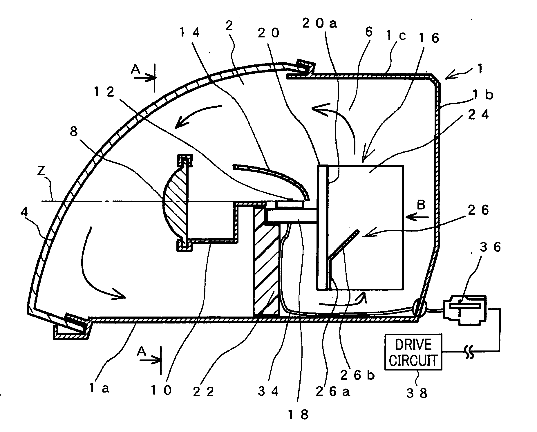
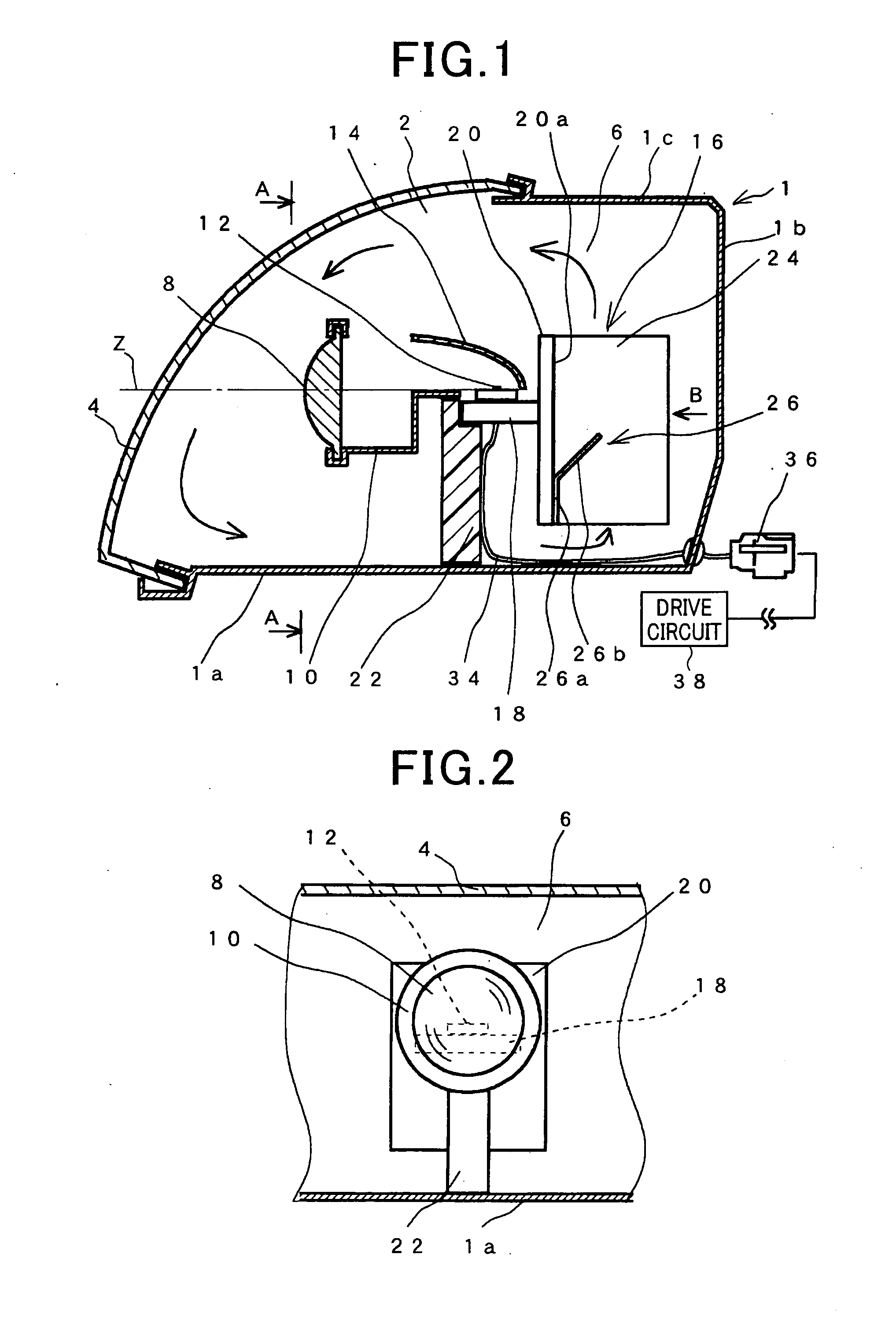
[0044]A description will now be given of the headlamp assembly according to the first embodiment of the present invention with reference to FIG. 1 to FIG. 6.

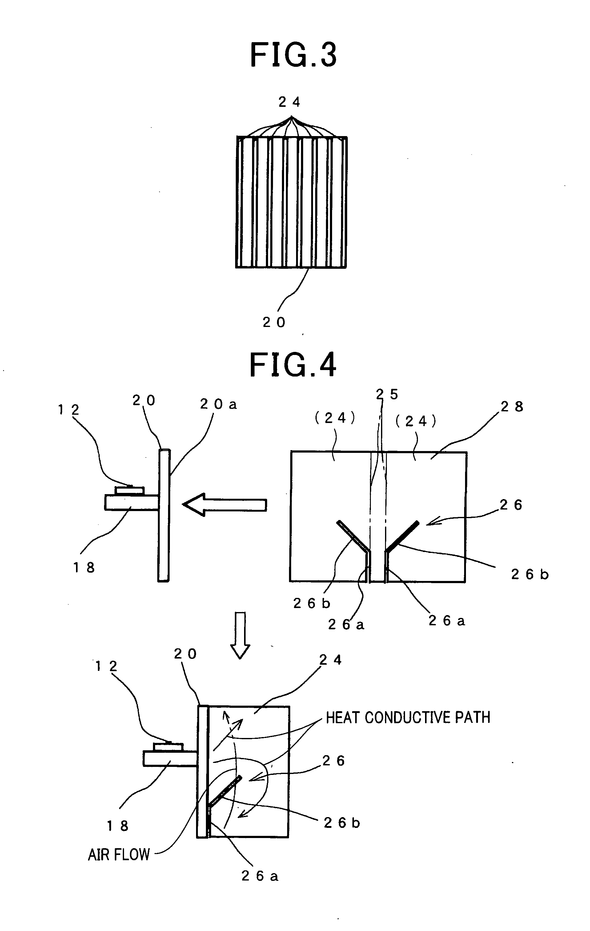
[0045]FIG. 1 is a schematic view showing a vertical cross section of a headlamp assembly mounted to a vehicle according to a first embodiment of the present invention. FIG. 2 is a view showing a cross section of the headlamp assembly along the A-A line shown in FIG. 1. FIG. 3 is a view showing a cross section of the radiating member composed of a plurality of the radiating fins 24 in the radiating member of the headlamp assembly when observed from the rear side designated by the arrow B shown in FIG. 1.

[0046]As shown in FIG. 1, the headlamp assembly according to the first embodiment is comprised of a housing case 1, a front lens cover 4 and other various types of components. A front part 2 of the housing case 1 is open. The front lens cover 4 is fitted and fixed to the front part 2 of the housing case 1 in order to approximately...

second embodiment

[0095]Next, a description will be given of the headlamp assembly according to the second embodiment of the present invention with reference to FIG. 7 to FIG. 10. The same components of the headlamp assemblies according to the first and second embodiments shown in FIG. 1 to FIG. 10 will be referred with the same reference numbers and the explanation of them is omitted for brevity.

[0096]FIG. 7 is a schematic view showing radiating fins 54 in the radiating member in the headlamp assembly according to the second embodiment of the present invention. As shown in FIG. 7, the radiating fin 54 does not have any slit. The radiating fin 54 is made by the following steps.

[0097]An upper one-third part of an aluminum thin plate 56 is bent 180 degrees along the dash-dotted line 57. The upper one-third part and the remained part of the aluminum thin plate 56 are overlapped together. This makes a difference in level (or a different level) designated by the straight line 62 shown in FIG. 7 on the sur...

third embodiment

[0130]A description will be given of the headlamp assembly according to the third embodiment of the present invention with reference to FIG. 11 to FIG. 15. FIG. 11 is a schematic view showing a vertical cross section of the headlamp assembly mounted to a vehicle according to the third embodiment of the present invention.

[0131]In the structure of the headlamp assemblies according to the first and second embodiments previously described, the light source 12 is fixed to the horizontal plate 18, and the horizontal plate 18 is fixed to the vertical plate 20.

[0132]On the other hand, as shown in FIG. 11, the headlamp assemblies according to the third embodiment has a mount member 88 of a square pillar shape. The light source 12 is fixed to the mount member 88. The mount member 88 is fixed to the vertical plate 20 in the radiating member 16. The drive circuit 90 is placed in the mount member 88. The drive circuit 90 supplies electric power to the light source 12.

[0133]FIG. 12 is an enlarged...


PUM


Abstract

In a light chamber formed in a housing case and a lens cover placed at a front part of the housing case in a headlamp assembly, a projection lens, a shade and a light source are arranged in line from the front side of the light chamber along an optical axis of the light source. A radiating member has radiating fins of a plate shape vertically placed in the light chamber, and radiates heat energy generated by the light source to surrounding air. A slit composed of a vertical slit part and an inclined-slit part is formed in each of the radiating fins. The formation of the slit generates a change of heat capacity and a temperature difference at upper and bottom parts of each of the radiating fins. The incline-slit part is extended from the top of the vertical slit part to the upper part of the radiating fin.

Description

CROSS-REFERENCE TO RELATED APPLICATION[0001]This application is related to and claims priority from Japanese Patent Application No. 2010-093161 filed on Apr. 14, 2010, the contents of which are hereby incorporated by reference.BACKGROUND OF THE INVENTION[0002]1. Field of the Invention[0003]The present invention relates to headlamp assemblies for motor vehicles, equipped with one or more radiating members capable of radiating heat energy generated by one or more light sources.[0004]2. Description of the Related Art[0005]There are various types of headlamp assemblies mounted to motor vehicles equipped with light emitting diodes. For example, Japanese patent No. JP4289268 has disclosed such a headlamp assembly comprised of a headlamp and a light emitting diode. In the headlamp assembly, a light projection lens, a shade and a light source are arranged in turn, and a reflector is arranged so that it faces the light source. The reflector reflects the light generated by the light source to...

Claims


Application Information

Patent Timeline
Patent Type & Authority Applications(United States)
IPC IPC(8): B60Q1/04
CPCF21S48/1159F21S48/321F21S48/328F21V29/76F21V29/004F21Y2101/02F21V29/71F21S48/335F21S41/148F21S45/47F21S45/48F21S45/49F21S45/60F21Y2115/10
Inventor TOMINAGA, MOTONORIKUME, SYOGOKAMIZONO, TSUTOMU
Owner NIPPON SOKEN
Why Eureka
Try Eureka