Antenna device and mobile terminal

A technology of antenna device and grounding wire, which is applied in the direction of antenna support/installation device, antenna, antenna parts, etc., can solve the problems affecting the overall appearance of the shell of the mobile terminal, so as to improve the bandwidth, ensure the integrity, and enhance the radiation performance Effect

Active Publication Date: 2016-07-20
GUANGDONG OPPO MOBILE TELECOMM CORP LTD
5 Cites 33 Cited by

AI-Extracted Technical Summary

Problems solved by technology

But the isolation strip will be clearly seen by consumers, thus ...

Method used

The micro-slit belt 130 shown in Fig. 1 comprises four arc-shaped micro-slits 1301, and the width of the slit is between 0.03 and 0.5mm. Because the width of the micro-slit is small enough, it is difficult to cause the attention of consumers, thereby ensuring that The metal shell 2 is integral, and the micro-slit strip 130 allows electromagnetic signals inside the metal shell 13 to radiate out. Moreover, the arc-shaped micro-slit strip 130 increases the length of the micro-slit strip 130 and enhances the radiation perform...

Abstract

The invention provides an antenna device. The antenna device comprises a radio frequency transceiving circuit, a matching circuit and a metal shell, wherein the matching circuit is electrically connected to the radio frequency transceiving circuit, the edge of the metal shell comprises an arc segment, the metal shell is provided with at least one micro-slot belt, the at least one micro-slot belt comprises an arc part, the arc part is matched with the arc segment of the metal shell, the radio frequency transceiving circuit is electrically connected with the metal shell through the matching circuit so that the metal shell is used as a radiation body of the antenna device, the metal shell is grounded by a grounding line, and a switch is arranged on the grounding line and is used for controlling on/off of the grounding line. With the antenna device according to the invention, the comprehensive appearance effect of a mobile terminal can be ensured, meanwhile, a signal of the antenna device can be prevented from being intervened, and the bandwidth of the antenna device is improved. The invention also provides the mobile terminal.

Application Domain

Technology Topic

Image

  • Antenna device and mobile terminal
  • Antenna device and mobile terminal
  • Antenna device and mobile terminal

Examples

  • Experimental program(1)

Example Embodiment

[0022] The technical solutions in the embodiments of the present invention will be clearly and completely described below with reference to the accompanying drawings in the embodiments of the present invention. Obviously, the described embodiments are only a part of the embodiments of the present invention, but not all of the embodiments. Based on the embodiments of the present invention, all other embodiments obtained by those of ordinary skill in the art without creative efforts shall fall within the protection scope of the present invention.
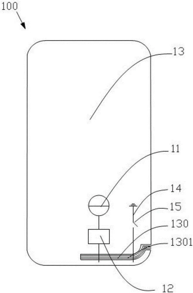
[0023] refer to figure 1 , shows the antenna device 100 according to the first embodiment of the present invention, the antenna device 100 includes a radio frequency transceiver circuit 11, a matching circuit 12 and a metal casing 13, the radio frequency transceiver circuit 11 is electrically connected with the metal casing 13 through the matching circuit 12, thereby The metal case 13 is used as a radiator of the antenna device 100 . And the metal casing 13 is grounded through a ground wire 14, and the ground wire 14 is provided with a switch 15 for controlling its on-off. Wherein, the edge of the gold outer shell 13 includes an arc-shaped section, and the metal shell 13 is provided with a micro-slit strip 130, and the micro-slit strip 130 includes an arc-shaped portion, and the arc-shaped portion is matched with the arc-shaped section of the metal shell 13, The micro-slit tape 130 extends non-penetratingly from the edge of the metal shell 13 to the inside of the metal shell 13, so that the metal shells 13 on both sides of the micro-slit tape 130 are connected to each other as a whole, and the micro-slit tape 130 The micro-slits 1301 in each extend along the short side of the housing 13 .
[0024] figure 1 The micro-slit tape 130 shown includes four arc-shaped micro-slits 1301, and the width of the slits is between 0.03 and 0.5 mm. Since the width of the micro-slits is small enough to not easily attract the attention of consumers, it can ensure the integrity of the metal casing 2. and the micro-slit strip 130 allows electromagnetic signals in the metal casing 13 to radiate out. And the arc-shaped micro-slot strip 130 increases the length of the micro-slot strip 130 and enhances the radiation performance of the antenna structure. In addition, the distance between two adjacent micro-slots 1301 is larger than the slit width of the micro-slots 1301, and metal strips are formed between the adjacent micro-slots 1301. The material of the metal strips is the same as that of the metal shell 13, so the In appearance, the integrity of the metal casing 13 is further ensured. The micro-slots 1301 are filled with non-signal shielding materials, so that electromagnetic signals of the antenna device 100 can be prevented from being shielded.
[0025] It should be noted that the number of micro-slots 1301 of the micro-slit strip 130 can be 3 to 20, and the number of micro-slits should be determined according to specific needs, such as meeting the requirements on the appearance of the metal casing 13 and the radiation of electromagnetic signals of the antenna device 100 condition.
[0026] like figure 1 As shown, the radio frequency transceiver circuit 11 is the feed source of the antenna device 100, and the function of the matching circuit 12 is to perform impedance matching and balance matching between the radio frequency transceiver circuit 11 and the metal casing 13, thereby reducing the return loss caused by the mismatch, In order to ensure that the antenna device 100 can work normally. In addition, the metal casing 13 is grounded through the ground wire 14, and the ground wire 14 is provided with a switch 15 for controlling its on-off. exist figure 1 Among them, when the switch 15 is closed, the metal casing 13 is grounded, and the frequency of the electromagnetic signal radiated by the antenna device 100 will be changed, so that the bandwidth of the antenna device 100 can be increased.
[0027] refer to figure 2 , showing the antenna device 200 according to the second embodiment of the present invention, the number of the micro-slot strip 230 is one, and the number and slot width of the micro-slot 2301 of the micro-slot strip 230 are the same as figure 1 The number and width of the micro-slits 1301 in the illustrated first embodiment are the same as figure 1 The antenna device 100 of the first embodiment shown is different in that the micro-slit strip 230 extends parallel to the short side of the metal casing 23 and penetrates the metal casing 23, thereby dividing the metal casing 23 into two independent metal regions 231 and 232. ,like figure 2 As shown, the area of ​​one of the metal regions 231 is larger than that of the other metal region 232 . In the antenna device 200 , the matching circuit 22 and the ground wire 24 with the switch 25 are both electrically connected to the metal region 232 . At this time, the metal region 231 can be coupled with the metal region 232 to radiate electromagnetic signals, while the The ground line 24 of the switch 25 can change the frequency of the electromagnetic radiation, thereby increasing the bandwidth of the antenna structure 200 . Of course, the matching circuit 22 and the ground wire 24 may be electrically connected to the metal region 231, and the matching circuit 22 and the ground wire 24 may also be electrically connected to the metal regions 231 and 232, respectively. When the matching circuit is electrically connected to one of the metal regions 231 and 232, due to the different sizes and structures of the metal region 231 and the metal region 232, the ground wire 24 is electrically connected to the different metal regions, and the electromagnetic signals that the antenna device 200 can transmit and receive are not limited. The frequency will change, so the ground wire 24 can be used to connect different metal regions to achieve the effect of frequency selection, thereby increasing the bandwidth of the antenna device 200 .
[0028] refer to image 3 , shows the antenna device 300 according to the second embodiment of the present invention, wherein the number of the micro-slot strips 330 is two, and the number and the slot width of the micro-slot strips 330 are the same as figure 1 The number and width of the micro-slots 1301 in the first embodiment shown are the same, and the two micro-slot strips 330 divide the metal shell 33 to form a first metal area 331 located in the middle and two areas respectively located in the first metal area 331. end of the second metal region 332 and the third metal region 333, such as figure 2 As shown, the area of ​​the first metal region 331 is larger than that of the second metal region 332 , and the area of ​​the second metal region 332 is equal to that of the third metal region 333 . In the antenna device 300 , the matching circuit 32 and the ground wire 34 with the switch 35 are both electrically connected to the third metal region 333 . At this time, both the first metal region 331 and the second metal region 332 can be connected to the third metal region 333 The coupling is formed to radiate the electromagnetic signal, and the ground wire 34 can change the frequency of the electromagnetic radiation, thereby increasing the bandwidth of the antenna structure 300 . Of course, there may also be other connection relationships between the matching circuit 32 and the ground wire 34 and the metal area. like image 3As shown, when the matching circuit 32 is electrically connected to one of the metal regions, due to the different sizes, structures and positions of the first metal region 331, the second metal region 332 and the third metal region 333, the ground wire 34 is connected to different metal regions During electrical connection, the frequency of electromagnetic signals that the antenna device 300 can transmit and receive will change, so the ground wire 34 can be used to connect different metal regions to achieve frequency selection, thereby increasing the bandwidth of the antenna device 300 .
[0029] It should be noted that the micro slits 131, 231 or 331 may intersect with each other. The micro-slot 21 may also extend through or partially along the long side of the metal casing, and the specific structure may depend on the requirements of the appearance and the specific parameters of the antenna device. The metal casing 2 can be a front casing or a back cover of the mobile terminal, and can also be a side frame of the mobile terminal.
[0030] In addition, preferably, both the radio frequency transceiver circuit 301 and the matching circuit 302 are arranged inside the mobile terminal. The mobile terminal refers to computer equipment that can be used on the move, including but not limited to mobile phones, notebooks, tablet computers, POS machines, vehicle-mounted computers, cameras, and the like.
[0031] What is disclosed above is only the preferred embodiment of the present invention, of course, it cannot limit the scope of the right of the present invention. Those of ordinary skill in the art can understand that all or part of the process of realizing the above-mentioned embodiment can be made according to the claims of the present invention. The equivalent changes of the invention still belong to the scope covered by the invention.

PUM

PropertyMeasurementUnit
Seam width0.03 ~ 0.4mm
tensileMPa
Particle sizePa
strength10

Description & Claims & Application Information

We can also present the details of the Description, Claims and Application information to help users get a comprehensive understanding of the technical details of the patent, such as background art, summary of invention, brief description of drawings, description of embodiments, and other original content. On the other hand, users can also determine the specific scope of protection of the technology through the list of claims; as well as understand the changes in the life cycle of the technology with the presentation of the patent timeline. Login to view more.

Similar technology patents

Self locking type worm gear-worm screw-threaded shaft elevator

InactiveCN101337648AGuaranteed integrityLarge number of envelope teethLifting devicesProduct processingSmooth surface
Owner:JIANGSU TAILONG MACHINERY GRP CO CO LTD

Classification and recommendation of technical efficacy words

  • Improve Radiation Performance
  • Guaranteed integrity

Rotating Electrical Machine

Owner:HITACHI ASTEMO LTD

Display Device

Owner:PANASONIC CORP

Metal frame mobile phone antenna

Owner:SHANGHAI AMPHENOL AIRWAVE COMM ELECTRONICS

Piston energy exchanger

InactiveCN1939605AIncrease powerImprove Radiation PerformanceMechanical vibrations separationDriven elementPiston
Owner:INST OF ACOUSTICS CHINESE ACAD OF SCI

Construction method for embedding pipelines in autoclave aerated concrete block walls

InactiveCN103758272AGuaranteed integritySave maintenance materialsBuilding componentsWater pipeAutoclaved aerated concrete
Owner:YONGSHENG CONSTR GRP
Why Eureka
Try Eureka