Systems, devices, and methods for proximity-based eye tracking

a proximity-based and eye tracking technology, applied in the field of eye tracking technologies, can solve the problems of negating the benefit, user not being able to see the external environment, and all of the wearable heads-up display devices available today are noticeably bulkier than a typical pair of eyeglasses or sunglasses

Active Publication Date: 2017-07-20
GOOGLE LLC
View PDF7 Cites 100 Cited by
  • Summary
  • Abstract
  • Description
  • Claims
  • Application Information

AI Technical Summary

Problems solved by technology

A wearable heads-up display (“WHUD”) is a head-mounted display that enables the user to see displayed content but does not prevent the user from being able to see their external environment.
Two challenges in the design of most WHUD devices are: i) maximizing functionality while at the same time minimizing the bulk of the WHUD unit itself, and ii) providing an appropriate interface for controlling and / or interacting with content displayed on the WHUD.
Given this, it is generally not appropriate for an interface for interacting with a WHUD to encumber the user's hand(s) as such would negate the benefit of the hands-free nature of the WHUD.
All of the wearable heads-up display devices available today are noticeably bulkier than a typical pair of eyeglasses or sunglasses.
A limitation of most eye tracking technologies developed to date is that they compromise the aesthetic design of a WHUD when incorporated therein, either directly due to bulk of the physical eye tracking components and / or indirectly due to large power requirements of the eye tracking components or processes, which necessitate a large battery to be incorporated into the WHUD.
Camera-based eye trackers consume a relatively large amount of power.
Additionally, the computational processing required to identify glints in such video / photo streams is quite high and therefore also consumptive of significant power.
This high power consumption means that camera-based eye trackers generally require a large power supply, so their incorporation into WHUDs typically contributes significant bulk to the overall aesthetic.

Method used


Image

  • Systems, devices, and methods for proximity-based eye tracking
  • Systems, devices, and methods for proximity-based eye tracking
  • Systems, devices, and methods for proximity-based eye tracking

Examples


Embodiment Construction

[0029]In the following description, certain specific details are set forth in order to provide a thorough understanding of various disclosed embodiments. However, one skilled in the relevant art will recognize that embodiments may be practiced without one or more of these specific details, or with other methods, components, materials, etc. In other instances, well-known structures associated with portable electronic devices and head-worn devices, have not been shown or described in detail to avoid unnecessarily obscuring descriptions of the embodiments.

[0030]Unless the context requires otherwise, throughout the specification and claims which follow, the word “comprise” and variations thereof, such as, “comprises” and “comprising” are to be construed in an open, inclusive sense, that is as “including, but not limited to.”

[0031]Reference throughout this specification to “one embodiment” or “an embodiment” means that a particular feature, structures, or characteristics may be combined ...


PUM


Abstract

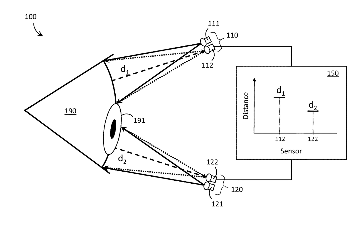
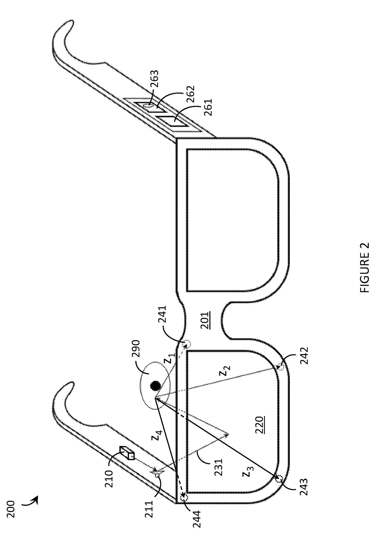
Systems, devices, and methods for proximity-based eye tracking are described. A proximity sensor positioned near the eye monitors the distance to the eye, which varies depending on the position of the corneal bulge. The corneal bulge protrudes outward from the surface of the eye and so, all other things being equal, a static proximity sensor detects a shorter distance to the eye when the cornea is directed towards the proximity sensor and a longer distance to the eye when the cornea is directed away from the proximity sensor. Optical proximity sensors that operate with infrared light are used as a non-limiting example of proximity sensors. Multiple proximity sensors may be used and processed simultaneously in order to provide a more accurate / precise determination of the gaze direction of the user. Implementations in which proximity-based eye trackers are incorporated into wearable heads-up displays are described.

Description

TECHNICAL FIELD[0001]The present systems, devices, and methods generally relate to eye tracking technologies and particularly relate to proximity-based eye tracking technologies that determine a user's gaze direction by monitoring the distance to the user's eye from one or more fixed location(s).BACKGROUNDDescription of the Related ArtWearable Heads-Up Displays[0002]A wearable heads-up display (“WHUD”) is a head-mounted display that enables the user to see displayed content but does not prevent the user from being able to see their external environment. When on the user's head, a WHUD secures at least one electronic display within an accessible field of view of at least one of the user's eyes, regardless of the position or orientation of the user's head. This at least one display is either transparent or at a periphery of the user's field of view so that the user is still able to see their external environment. Examples of WHUDs include: the Google Glass®, the Optinvent Ora®, the Ep...

Claims


Application Information

Patent Timeline
Patent Type & Authority Applications(United States)
IPC IPC(8): G06F3/01G01S17/42G01S17/58G02B27/01G01S17/66G01S17/10G01S17/32G01S17/87
CPCG06F3/013G02B27/0172G02B27/0176G02B2027/014G01S17/58G01S17/42G02B2027/0178G01S17/66G01S17/08G01S17/10G01S17/32G01S17/46G01S17/87G01S17/88G06F1/163G06F3/011G02B27/0093
Inventor VIDAL, MELODIECHAPESKIE, JAKE
Owner GOOGLE LLC
Why Eureka
Try Eureka