Selectorized dumbbell with a weight selector having a continuous periphery that encloses an open interior

a technology of selector and weight, which is applied in the field of selectorized dumbbells, can solve the problems of user's incorrect installation of u-shaped connecting pins, damage or failure of connecting pins, and dislodgement of weights from handles

Active Publication Date: 2017-07-27
POWERBLOCK HLDG
View PDF6 Cites 11 Cited by
  • Summary
  • Abstract
  • Description
  • Claims
  • Application Information

AI Technical Summary

Problems solved by technology

However, while it is unlikely to happen, it is possible for a user to incorrectly install the U-shaped connecting pin by inserting one connecting prong on one side of the pin beneath the rails of the selected weight and the other connecting prong on the other side of the pin beneath the rails of the weight either above or below the selected weight.
Since the weights are not correctly held in their most stable configuration when they are cross-pinned, there is a small possibility of damage or failure of the connecting pin and consequent dislodgement of the weights from the handle.
This is obviously a disadvantage.
However, the use of magnets increases the manufacturing cost of the connecting pin and increases the danger of disconnection in a cross-pinned situation since the cross member of the connecting pin no longer lies flush against a single rail.
In addition, even when the connecting pin is correctly installed and the magnetic latch formed by the magnets is in place, very vigorous exercise in certain instances can very rarely overcome the magnetic attraction to cause the connecting pin to begin to detach from the handle.
This is also obviously a disadvantage particularly when the dumbbell is being used in a setting, such as a fitness center or gym, where a particular user may not be intimately familiar with using selectorized dumbbells and correctly installing the connecting pin.

Method used


Image

  • Selectorized dumbbell with a weight selector having a continuous periphery that encloses an open interior
  • Selectorized dumbbell with a weight selector having a continuous periphery that encloses an open interior
  • Selectorized dumbbell with a weight selector having a continuous periphery that encloses an open interior

Examples


Embodiment Construction

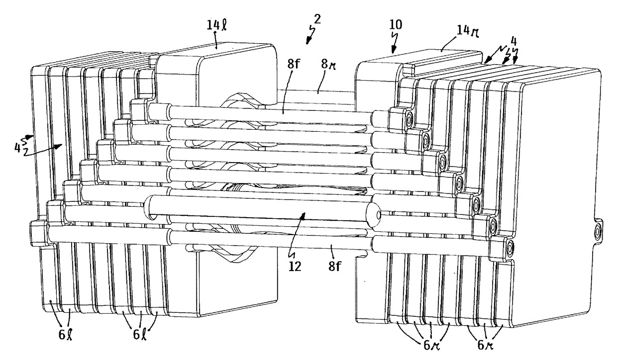
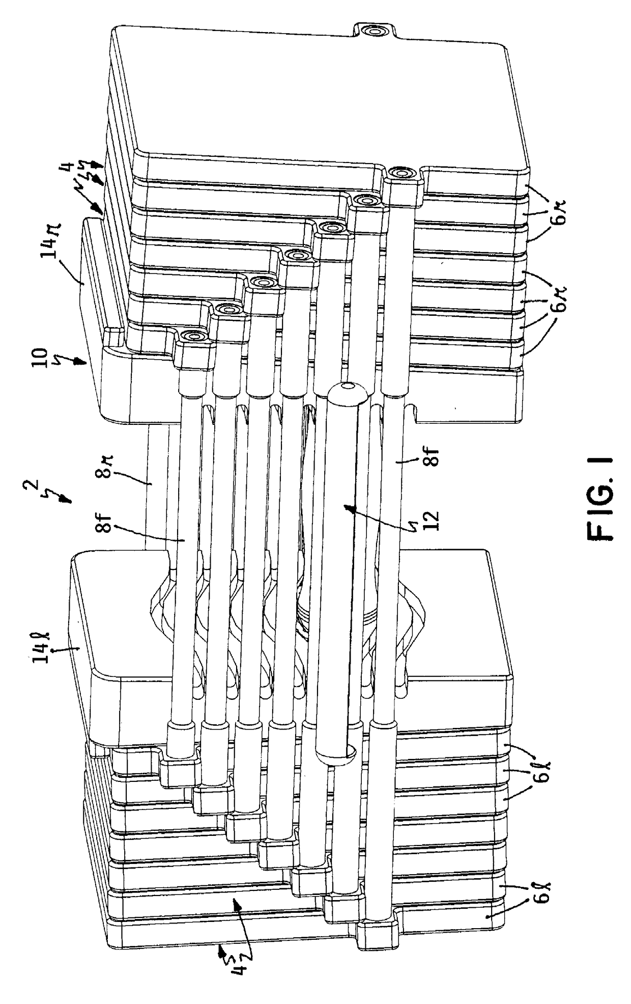
[0019]One embodiment of a selectorized dumbbell according to this invention is indicated generally as 2 in FIG. 1. Dumbbell 2 is of the general type disclosed in U.S. Pat. Nos. 5,637,064 and 7,775,947, which are hereby incorporated by reference. See in particular the dumbbell disclosed in FIGS. 6-12 of the 947 patent and the accompanying description thereto. While such patents may be referred to for a complete description of dumbbell 2, a review of the basic components of dumbbell 2 is in order herein.

[0020]Referring now to FIG. 1, dumbbell 2 comprises a plurality of nested weights 4, a handle 10, and a weight selector 12. Each nested weight 4 comprises a left weight plate 6l and a right weight plate 6r that are joined together in a laterally spaced apart orientation by a front rail 8f and a rear rail 8r that connect weight plates 6l and 6r together. Beginning with the innermost weight 4 and working outwardly to the outermost weight 4, rails 8 get progressively longer and connect to...


PUM


Abstract

A selectorized dumbbell has a plurality of nested weights that provide a stack of left weight plates and a stack of right weight plates. A handle is dropped between the stacks and a selector is inserted into one of a plurality of vertically spaced positions on the handle to couple a selected number of the weights to the handle. The selector has a continuous periphery enclosing an open interior. A user who is exercising with the dumbbell will be alerted to unintended dislodgement of the selector since a portion of the selector's periphery will contact a portion of the user's grip hand, wrist or forearm during such dislodgement. This prevents complete dislodgement and prompts the user to restore the selector to a fully installed position. Side walls of the selector may become curved when the selector is installed to provide an additional frictional force resisting dislodgement of the selector.

Description

TECHNICAL FIELD[0001]This invention relates to exercise equipment and, more particularly, to a selectorized dumbbell having a user selectable exercise mass that is adjustable by selectively varying the position of a weight selector relative to a handle of the dumbbell. This invention further relates to a weight selector that is resistant to being inadvertently dislodged from the handle or incorrectly installed on the handle.BACKGROUND OF THE INVENTION[0002]U.S. Pat. No. 5,637,064 to Towley et al, which is assigned to the assignee of this invention, discloses an existing selectorized dumbbell that is known as the PowerBlock®. In this dumbbell, there are a plurality of nested weights each of which comprises a left weight plate and a right weight plate that are joined together by a pair of front and rear rails. The left and right weight plates of the nested weights are disposed in nested left and right weight plate stacks that are spaced apart from one another by the length of the fron...

Claims


Application Information

Patent Timeline
Patent Type & Authority Applications(United States)
IPC IPC(8): A63B21/075A63B21/072A63B23/12A63B21/00
CPCA63B21/075A63B21/00065A63B23/12A63B21/0728A63B21/0726
Inventor TOWLEY, III, CARL K.
Owner POWERBLOCK HLDG
Why Eureka
Try Eureka