
Illuminated keyswitch

a keycap and illumination technology, applied in the field of keyswitch, can solve the problems of limiting the structural design of the light-penetrant portion of the keycap (including the size and location thereof), affecting the light emitted by the light source toward the keycap, and further limiting the design of the light-penetrant portion of the keycap

Active Publication Date: 2017-08-03
DARFON ELECTRONICS (SUZHOU) CO LTD +1
View PDF12 Cites 4 Cited by
  • Summary
  • Abstract
  • Description
  • Claims
  • Application Information

AI Technical Summary

Benefits of technology

The illuminated keyswitch in this invention uses a light-guiding rod to make sure the light is not affected by the lift mechanism. This means that every part of the cap can receive the light, so any part can be designed as a light-penetrable part, which can be of any size. This solves the problem in the prior art where the path of the light is limited, which means the design of the light-penetrable part of the key is limited.

Problems solved by technology

In general, the light source (e.g. an LED component) is usually disposed on the base, so if there are other components (e.g. mechanism for moving the keycap up and down relative to the base) disposed between the keycap and the base, the light emitted by the light source toward the keycap will be interfered.
On the whole, only a specific portion of the keycap can receive sufficient and uniform light, which limits the structural design of the light-penetrable portion of the keycap (including the size and location thereof).
Therefore, in the structural configuration of the illuminated keyswitches, the light source provides illumination light only in a single direction so the keycap as a whole cannot be illuminated uniformly by the illumination light, which further limits the design of the light-penetrable portion of the keycap.

Method used


Image

  • Illuminated keyswitch
  • Illuminated keyswitch
  • Illuminated keyswitch

Examples


Embodiment Construction

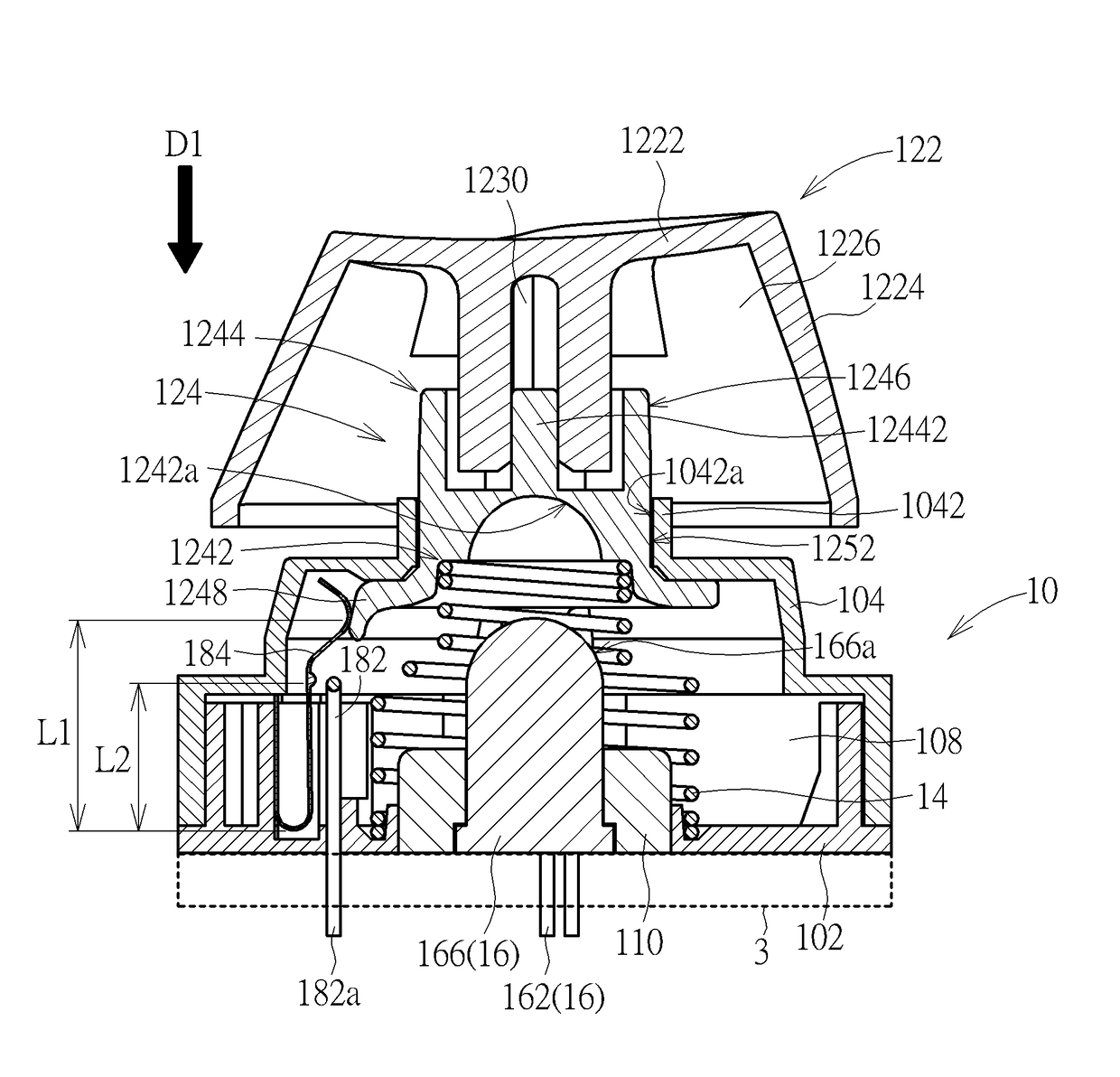
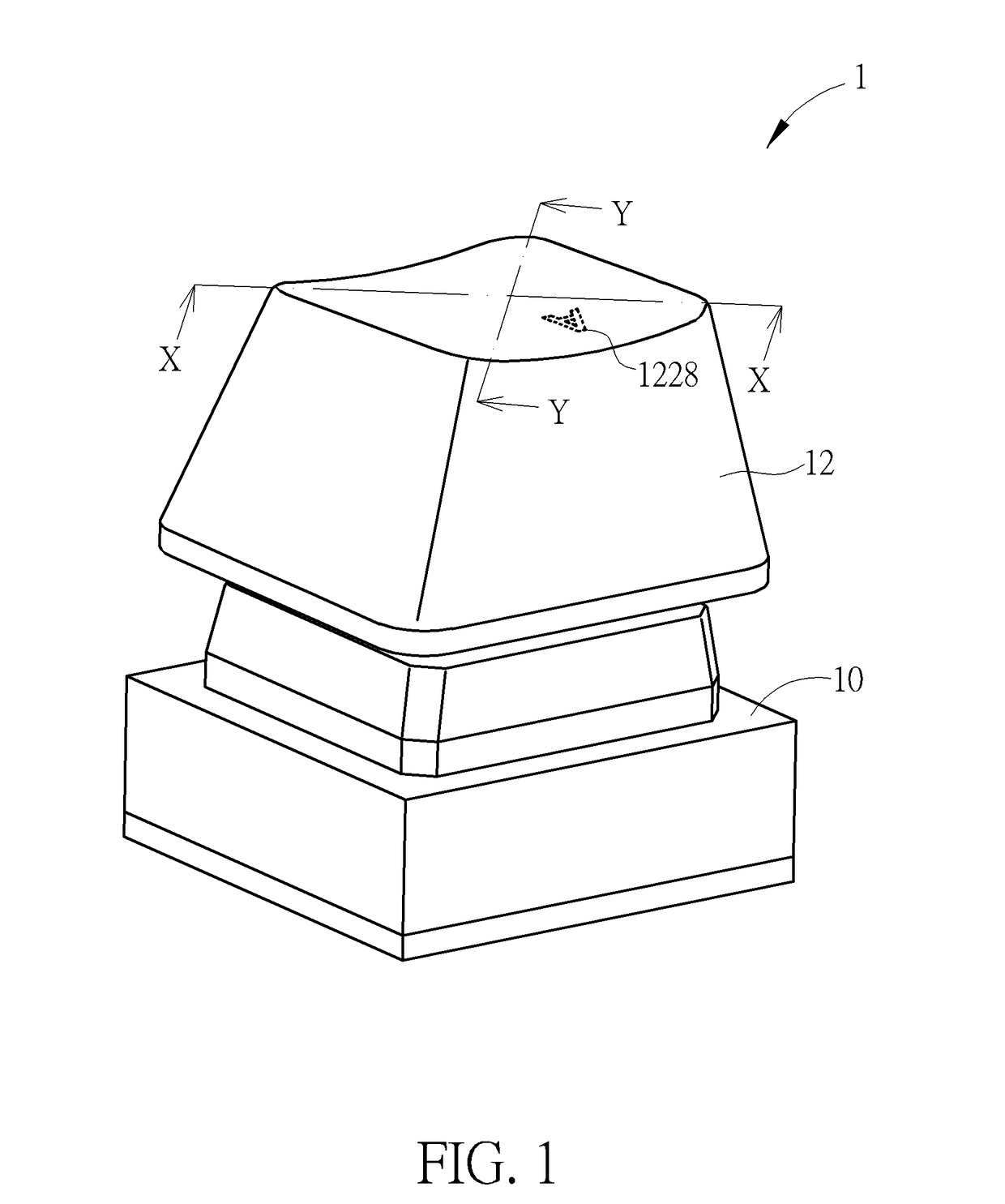
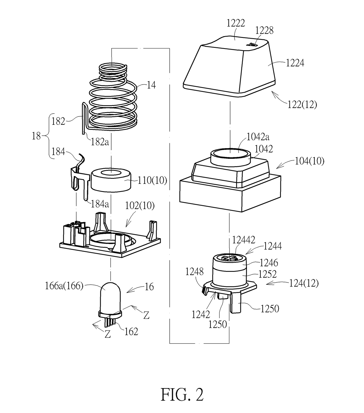
[0021]Please refer to FIG. 1 to FIG. 4. An illuminated keyswitch 1 of an embodiment according to the invention includes a base 10, a keycap 12, a lift mechanism 14, a light source 16, and a switch 18. The keycap 12 is disposed above the base 10. The lift mechanism 14 is disposed between the base 10 and the keycap 12, so that the keycap 12 is movable parallel to a direction D1 (indicated by an arrow in FIG. 3 and FIG. 4) toward or away from the base 10 through the lift mechanism 14. Therein, in the view point of FIG. 3 and FIG. 4, the direction D1 is equivalent to a vertical direction. In the embodiment, the lift mechanism 14 is but not limited to a spring. Therefore, when the keycap 12 is pressed to move toward the base 10 parallel to the direction D1, the lift mechanism 14 is also compressed and stores elastic energy accordingly. When the keycap 12 is no longer pressed, the stored elastic energy can be released so as to drive the keycap 12 to move away from the base 10 parallel to ...


PUM


Abstract

An illuminated keyswitch includes a base, a keycap, a lift mechanism, and a light source. The keycap includes a cap body and a light guiding rod. The lift mechanism is connected to between the light guiding rod and the base, such that the keycap can vertically move relative to the base through the lift mechanism. The light source is disposed between the light guiding rod and the base and emits light toward the light guiding rod. The light enters the light guiding rod through an end portion of the light guiding rod and then emits out the light guiding rod from another end portion of the light guiding rod and a side surface adjacent to the another end portion toward the cap body. Thereby, the whole cap body can receives relatively uniform back light.

Description

BACKGROUND OF THE INVENTION[0001]1. Field of the Invention[0002]The invention relates to a keyswitch, and especially relates to an illuminated keyswitch with backlight.[0003]2. Description of the Prior Art[0004]There is a kind of illuminated keyswitches using a light source (which may be spot light or surface light) disposed below the keycap for producing backlight to the keycap. The backlight can be observed by a user outside the keyswitch through the periphery or a light-penetrable portion of the keycap, which results in an illumination effect (e.g. by which the user can know the position of the key) or an indication effect (e.g. by which the user can know the name of the key). In general, the light source (e.g. an LED component) is usually disposed on the base, so if there are other components (e.g. mechanism for moving the keycap up and down relative to the base) disposed between the keycap and the base, the light emitted by the light source toward the keycap will be interfered....

Claims


Application Information

Patent Timeline
IPC IPC(8): H01H13/02F21V8/00
CPCH01H13/023H01H2219/0621G02B6/0008G02B6/0006H01H1/24H01H3/42H01H2205/004H01H2219/014H01H2219/056H01H2219/062
Inventor LIAO, RUI-MINGYEN, CHIH-CHUNGLIU, CHIA-HUNG
Owner DARFON ELECTRONICS (SUZHOU) CO LTD
Learn More