Image forming apparatus

a technology of forming apparatus and forming lever, which is applied in the direction of electrographic process apparatus, instruments, optics, etc., can solve the problems of increased likelihood of force required to perform the opening/closing operation of the cover, poor usability of the user's operation of the locking/unlocking position of the cover by a lever, and deterioration of the operation sound, so as to reduce the occurrence of an impact sound without impairing usability

Active Publication Date: 2017-09-07
CANON KK
View PDF4 Cites 3 Cited by
  • Summary
  • Abstract
  • Description
  • Claims
  • Application Information

AI Technical Summary

Benefits of technology

[0012]The present invention has an object of providing a locking mechanism ...

Problems solved by technology

However, such a configuration in which a user operates the locking/unlocking position of a cover by a lever is not excellent in usability since it is difficult to determine a handle position or the user is not necessarily allowed to intuitively recognize an operating direction and an opening/closing direction.
As described above, while being effective in terms of improving usability, the toggle mechanism does cause deterioration in an operation sound.
In recent years, since some laser beam printers perform the pop-up operation of a toner cartridge in conjunction with a cover or hold one side of a sheet p...

Method used


Image

  • Image forming apparatus
  • Image forming apparatus
  • Image forming apparatus

Examples


first embodiment

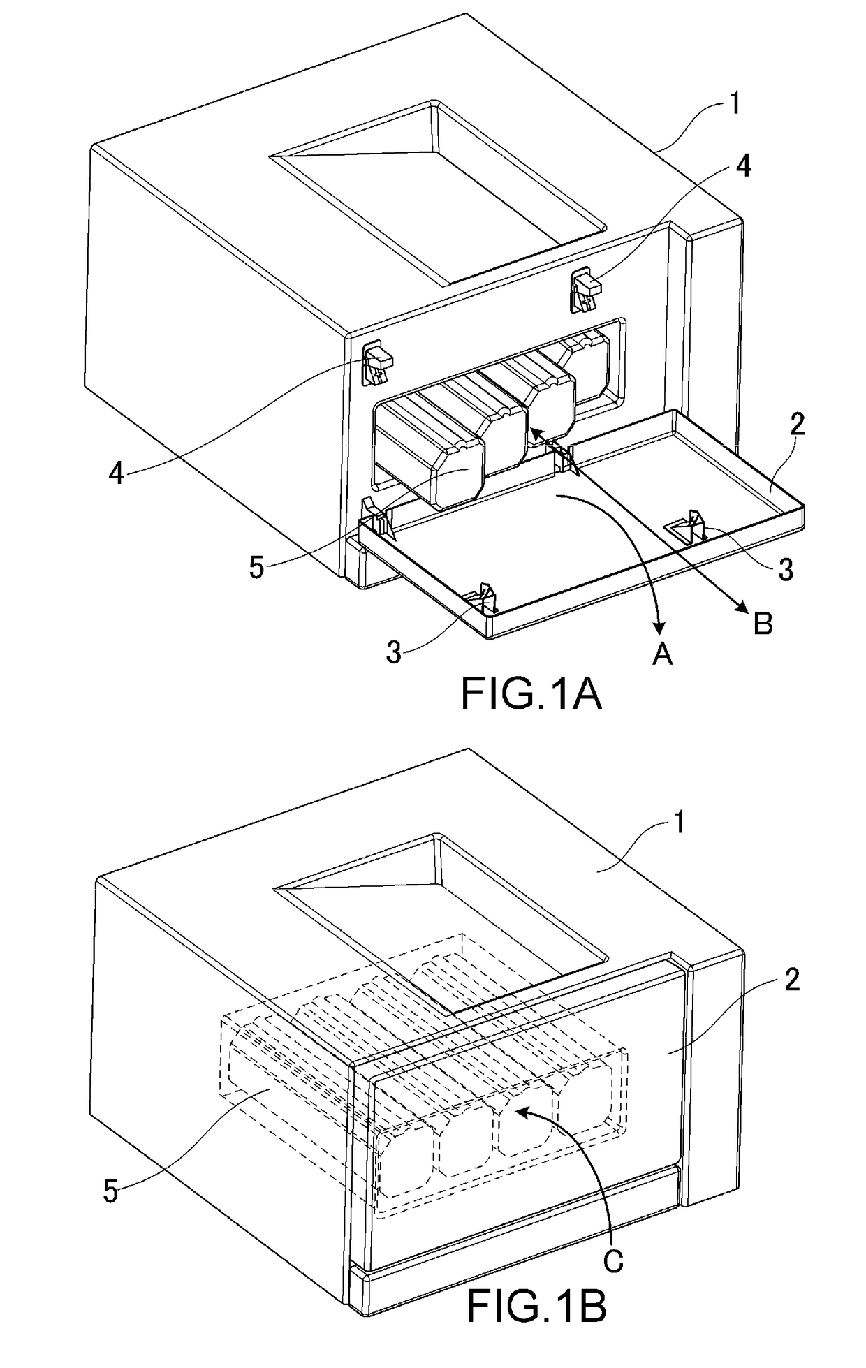
[0039]FIGS. 1A and 1B are schematic perspective views of an image forming apparatus to which a locking mechanism according to an embodiment of the present invention is applied. FIGS. 1A and 1B show a state in which a front cover 2 is opened with respect to an image forming apparatus main body 1 and a state in which the front cover 2 is closed with respect to the image forming apparatus main body 1, respectively.

[0040]As shown in FIG. 1A, the front cover 2 serving as an opening / closing door is configured to rotate in an arrow A direction with respect to the apparatus main body 1 to be allowed to open the inside of the apparatus main body 1, and allows a user to access the inside of the apparatus main body 1. The arrow A direction is a rotating direction about an axis parallel to a horizontal surface representing an installation surface for the image forming apparatus. Process cartridges 5 are cartridges obtained by integrating processing means such as a photosensitive member and deve...

second embodiment

[0066]A description will be given, with reference to FIGS. 12 to 17, of a locking mechanism according to a second embodiment of the present invention. The main configuration of an image forming apparatus main body 1 is the same as that of the first embodiment. Therefore, the points of the second embodiment different from those of the first embodiment will be mainly described. The items of the second embodiment that will be not described here are the same as those of the first embodiment.

[0067]FIG. 12 is a schematic perspective view showing a state in which a jam processing cover 22 is opened with respect to the image forming apparatus main body 1. As shown in FIG. 12, the jam processing cover 22 serving as an opening / closing door is configured to rotate in an arrow A direction with respect to the apparatus main body 1 to open a transporting path for a recording material inside the apparatus main body 1 to an outside such that a user is allowed to access the recording material stoppe...


PUM


Abstract

An image forming apparatus includes a locking mechanism that locks an opening/closing door to an engagement position, the locking mechanism having a engaged member and an urging member that urges the engaged member; and an engagement member that is provided on the door and engages the engaged member; wherein an urging force acting on the engaged member from the urging member is converted from a first urging force to press out the engagement member to a second urging force to draw the engagement member into the engagement position when the door is closed; wherein the engagement member has a contacted region and the engaged member has a contact region that comes in contact with the contacted region; and wherein the contacted region elastically deforms when the contact region comes in contact with the contacted region.

Description

BACKGROUND OF THE INVENTION[0001]Field of the Invention[0002]The present invention relates to an image forming apparatus such as a copier and a printer.[0003]Description of the Related Art[0004]Electrophotographic image forming apparatuses such as printers and copiers in which users replace components such as toner cartridges by opening / closing covers have been known, and various systems have been employed as locking mechanisms for the covers. For example, Japanese Patent Application Laid-open No. 2004-138775 discloses a configuration in which a user operates a handle to switch the position of a locking claw between a locking position and an unlocking position.[0005]However, such a configuration in which a user operates the locking / unlocking position of a cover by a lever is not excellent in usability since it is difficult to determine a handle position or the user is not necessarily allowed to intuitively recognize an operating direction and an opening / closing direction. Therefore,...

Claims


Application Information

Patent Timeline
IPC IPC(8): G03G15/00
CPCG03G21/1647G03G21/1633G03G21/1676G03G2215/0132
Inventor INADA, SEIJI
Owner CANON KK
Why Eureka
Try Eureka