
Method of inspecting ultraviolet curable resin for optical fiber and method of manufacturing optical fiber

a technology of ultraviolet curable resin and optical fiber, which is applied in the direction of optical fiber, optical apparatus testing, instruments, etc., can solve the problems of low temperature loss, appearance defect, difficulty in visual determination, etc., and achieve the effect of preventing the occurrence of loss increase and appearance d

Active Publication Date: 2016-09-29
SUMITOMO ELECTRIC IND LTD
View PDF0 Cites 4 Cited by
  • Summary
  • Abstract
  • Description
  • Claims
  • Application Information

AI Technical Summary

Benefits of technology

The present invention relates to a method for inspecting and manufacturing an optical fiber using ultraviolet curable resin. The method is designed to prevent issues such as loss increase and appearance defects in the manufactured optical fiber by detecting if air bubbles are mixed into the resin. This helps to ensure the quality of the optical fiber is not compromised during the manufacturing process.

Problems solved by technology

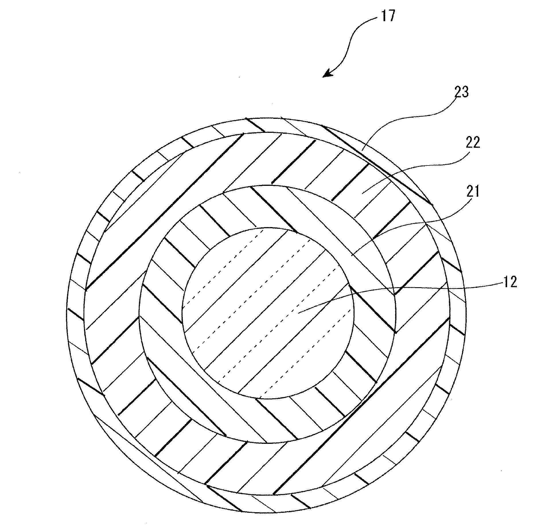
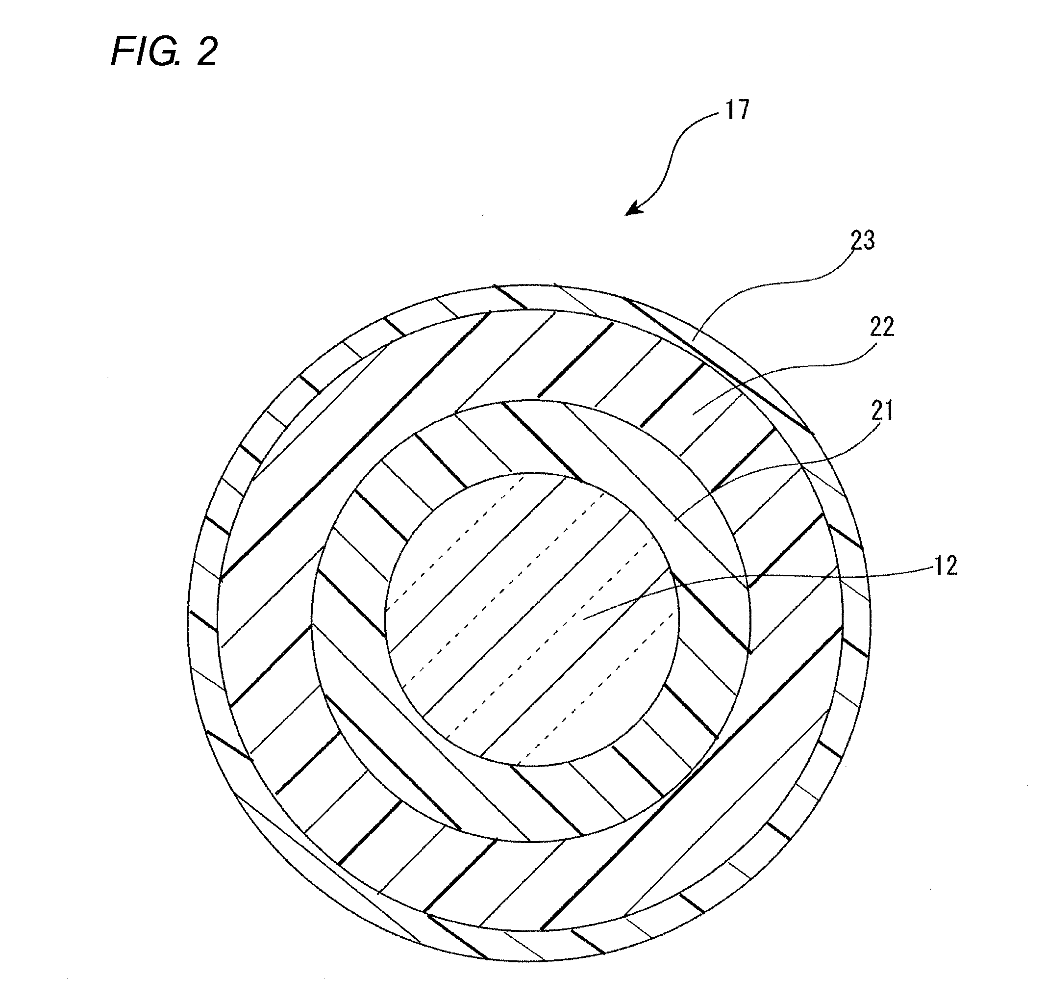
If the air bubbles are present in the resin of the optical fiber, the resin unevenly shrinks in a circumferential direction and thus a bare optical fiber is pressurized, which causes a loss increase (low-temperature loss) particularly when a temperature is set to be low.
In addition, unevenness such as a hump is formed on the surface of the resin, and thereby an appearance defect, or the like occurs in the optical fiber.
In addition, it is difficult to visually determine whether or not the air is deflated to the extent that no problems are caused in the manufacturing, and even if it is visually determined that the air bubbles are not present in the resin, there is a possibility that the air bubbles are generated after the bare optical fiber is coated with the ultraviolet curable resin for an optical fiber.

Method used


Image

  • Method of inspecting ultraviolet curable resin for optical fiber and method of manufacturing optical fiber
  • Method of inspecting ultraviolet curable resin for optical fiber and method of manufacturing optical fiber
  • Method of inspecting ultraviolet curable resin for optical fiber and method of manufacturing optical fiber

Examples


example

[0062]Hereinafter, Example will be described.

[0063]As illustrated in FIG. 6, the degree of air bubbles which are mixed into the ultraviolet curable resin for an optical fiber is inspected through the method of inspecting the ultraviolet curable resin for an optical fiber according to the above-described embodiment. As an inspecting target, the ultraviolet curable resin 42 for an optical fiber having viscosity of 1.2 Pa·s to 6.2 Pa·s at a temperature of 25±5° C. is used. The temperature of the ultraviolet curable resin 42 for an optical fiber is stably set to be 25±5° C. before performing the inspection. The test tube 41 which has an inner diameter of 25 mm and a length of 20 cm is used. In addition, the ultraviolet curable resin 42 for an optical fiber is put into the test tube 41 such that the liquid level becomes 15±1 cm, it is confirmed that the liquid level 42a becomes constant in the test tube, and then the test tube 41 is decompressed such that the pressure in the test tube 41...


PUM

PropertyMeasurementUnit
temperatureaaaaaaaaaa
viscosityaaaaaaaaaa
pressureaaaaaaaaaa

Abstract

A method of inspecting a degree of air bubbles which are mixed into an ultraviolet curable resin for an optical fiber having viscosity of 1.2 Pa·s to 6.2 Pa·s at a temperature of 25±5° C., is performed in such a manner that the ultraviolet curable resin for an optical fiber which is an inspecting target is put into a sealed apparatus, then the inside of the sealed apparatus is decompressed to be a predetermined pressure, and then the sealed apparatus is left to stand as it is for a predetermined time. If a ratio of the volume expansion of the ultraviolet curable resin for an optical fiber is equal to or less than a predetermined threshold, the ultraviolet curable resin for an optical fiber is recognized as an accepted product.

Description

CROSS-REFERENCE TO RELATED APPLICATION[0001]The present application claims the benefit of priority of Japanese Patent Application No. 2015-060411, filed on Mar. 24, 2015, which is incorporated herein by reference.BACKGROUND[0002]1. Technical Field[0003]The present invention relates to a method of inspecting an ultraviolet curable resin for an optical fiber and a method of manufacturing an optical fiber.[0004]2. Related Art[0005]A technique of defoaming a highly viscous liquid in such a manner that the highly viscous liquid is decompressed and is put into a sealed container, and then is centrifugally separated by rotating the sealed container (for example, refer to Japan Patent Publication No. S62-210009 (JP-A-S62-210009) has been known. In addition, the specification of Chinese Patent Publication No. 103212220 (CN-A-103212220) discloses a revolving speed, a time of a resin, and the like at the time of defoaming air bubbles in the resin by revolving a container including the resin th...

Claims


Application Information

Patent Timeline
Patent Type & Authority Applications(United States)
IPC IPC(8): G01N7/14C09D201/00G02B6/02C09D5/00
CPCG01N7/14G02B6/02395C09D201/00C09D5/00G01N33/442G02B6/036G01M11/088B29B7/845B29B7/106
Inventor YAMAGUCHI, AKIHISAKATO, MASAYUKITSUBAKIYAMA, HITOSHI
Owner SUMITOMO ELECTRIC IND LTD
Learn More