
A kind of hole reaming groove and hole reaming method for wet process black silicon machine

A black silicon, wet process technology, applied in sustainable manufacturing/processing, climate sustainability, semiconductor devices, etc., can solve problems such as unreasonable temperature control of liquid medicine, uneven mixing of liquid medicine, etc., to ensure stability and reliability. The uniformity of appearance, the effect of promoting mixing uniformity, and ensuring the quality of preparation

Active Publication Date: 2019-05-03
无锡琨圣智能装备股份有限公司
View PDF5 Cites 0 Cited by
  • Summary
  • Abstract
  • Description
  • Claims
  • Application Information

AI Technical Summary

Problems solved by technology

[0003] In order to overcome the shortcomings of the above-mentioned prior art, the present invention provides a reaming tank and a reaming method for wet-process black silicon machines to solve the unreasonable control of the temperature of the liquid medicine and the improper mixing of the liquid medicine in the prior art. uniform problem

Method used


Image

  • A kind of hole reaming groove and hole reaming method for wet process black silicon machine
  • A kind of hole reaming groove and hole reaming method for wet process black silicon machine
  • A kind of hole reaming groove and hole reaming method for wet process black silicon machine

Examples


Embodiment 1

[0031] Based on the above-mentioned reaming tank for wet-process black silicon machine, the present invention also discloses a method for reaming holes of wet-process black silicon, which is specifically as follows:

[0032] (1) First, place the black silicon neatly in the flower basket, put the flower basket into the main tank at a speed of 2-5cm / s, set the lower end nested on the positioning frame, and then soak in the main tank for 10-30s Finally, lift the flower basket, and then soak the next set of black silicon;

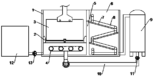
[0033] (2) After soaking 5 to 15 groups of black silicon, add liquid to the main tank through the liquid replenishment tank. At this time, the amount of liquid in the main tank increases so that it overflows from the top of the baffle to the auxiliary tank;

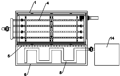
[0034] (3) The liquid that overflows into the auxiliary tank flows sequentially on the deflector, and during the flow, it contacts the capillary tube equipped with cooling water to cool down, and finally t...

Embodiment 2

[0038] The difference between this embodiment and Embodiment 1 lies in: In step (1), the flower basket is put into the main tank at a speed of 5-15 cm / s, and soaked for 30-60 s.

Embodiment 3

[0040] The difference between this embodiment and embodiment 2 is that in step (1), the flower basket is put into the main tank at a speed of 15-25 cm / s, and soaked for 60-120 s.

[0041] Comparing the black silicon structures made based on the above three examples, it is concluded that in Example 1, due to the short immersion time, the reaction on the surface of the black silicon is not sufficient; in Example 3, due to the faster placing speed, the disturbance of the liquid is reduced The aesthetics of the black silicon surface, so embodiment 2 is the best embodiment, the flower basket placement speed is 5-15cm / s, and the soaking time of the black silicon is 30-60s.


PUM


Abstract

The invention discloses a reaming groove for a wet black silicon machine and a reaming method of the reaming groove. The reaming groove comprises a main groove, an auxiliary groove, a cold-heat exchanger and a liquid guide tube for forming a liquid flow circuit; design of the main groove and the auxiliary groove is mainly used for releasing certain heat after reaction of a silicon wafer is completed, so that overflowing liquid medicine is effectively cooled through the design of capillary tubes in the auxiliary groove; meanwhile, the cold-heat exchanger is also arranged, so that secondary cooling for the liquid medicine is achieved and the preparation quality of black silicon is effectively ensured; and the liquid medicine overflows into the auxiliary groove from the main groove, and meanwhile, the liquid medicine is conveyed through liquid inlet pipes in which a plurality of liquid outlet holes are distributed, so that the uniformity of a chemical solution is ensured to the maximum extent.

Description

technical field [0001] The invention relates to a black silicon hole-enlarging device and a hole-enlarging method, in particular to a hole-enlarging groove and a hole-enlarging method for a wet-process black silicon machine. Background technique [0002] As an environmentally friendly and renewable energy technology, photovoltaic power generation technology has developed rapidly in recent years, but how to further improve the conversion efficiency of batteries and reduce battery production costs has become the main problem facing the development of the industry. The very important step of hole expansion in the wet black silicon process needs to be carried out in a low temperature HF / HNO3 mixed solution, because the hole expansion process has extremely high requirements on the uniformity of the chemical solution and the reaction temperature. And during the actual operation of the machine, a certain amount of chemical agents will be added for each batch of silicon wafers to su...

Claims


Application Information

Patent Timeline
Patent Type & Authority Patents(China)
IPC IPC(8): H01L31/18
CPCH01L31/1876Y02P70/50
Inventor 邵玉林
Owner 无锡琨圣智能装备股份有限公司
Learn More