Electric vehicle high current charging cable

A technology for charging cables and electric vehicles, which is applied in the direction of power cables, insulated cables, cables, etc., which can solve the problems of unguaranteed service life of cables, increase of charging current, heating of cables, etc., to facilitate automatic operation, save cooling costs, The effect of increasing the contact area

Active Publication Date: 2019-07-16
深圳宝新电线电缆制造有限公司
View PDF9 Cites 0 Cited by
  • Summary
  • Abstract
  • Description
  • Claims
  • Application Information

AI Technical Summary

Problems solved by technology

At present, the DC charging pile with the largest power on the market is 150KW, the charging current is 250A, and the charging time is nearly 1 hour. Such a long charging time greatly affects the enthusiasm of users to use electric vehicles.
In order to increase the charging speed of electric vehicles, it is necessary to further increase the charging current, which will cause severe heating of the cable
The conventional countermeasure adopted is to increase the section of the cable, but the section of the cable currently on the market is too large. If the section of the cable is increased, it will be difficult for the user to operate normally. Therefore, it is difficult to increase the charging power by using the conventional method. The method of forced cooling reduces the heating of the cable, increases the charging current and increases the charging power while maintaining the same cross section of the cable
[0003] In the prior art, most of the heat dissipation pipes are made of metal materials with high hardness and are not easy to be crimped, which cannot be adapted to the electric vehicle charging lines that require frequent movement and bending, and have strict requirements on the joints. Some heat dissipation pipes are also equipped with heat dissipation holes to make the cooling medium Direct contact with the cable conductor is easy to cause oxidation and corrosion to the conductor, which has certain safety hazards. Impurities can easily enter the insulation layer to cause water trees or even breakdown. The service life of the cable cannot be guaranteed, and most of the pipes are one-way cooling pipes. lower

Method used


Image

  • Electric vehicle high current charging cable
  • Electric vehicle high current charging cable
  • Electric vehicle high current charging cable

Examples


Embodiment Construction

[0024] It should be understood that the specific embodiments described here are only used to explain the present invention, not to limit the present invention.

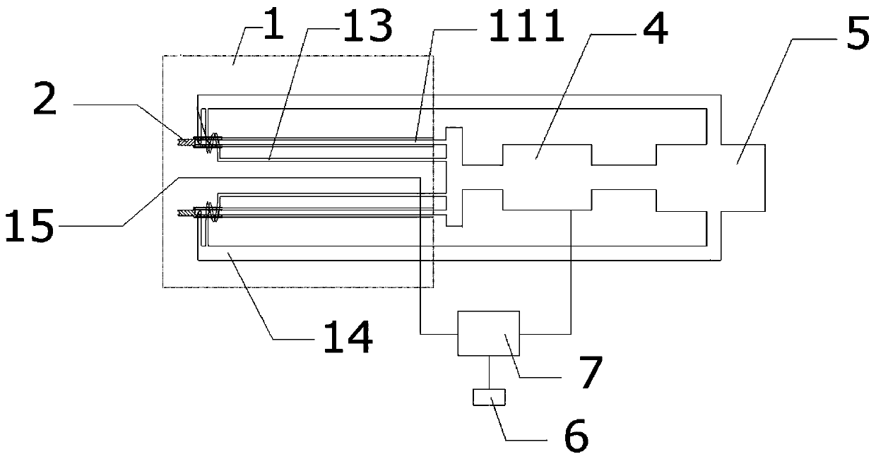
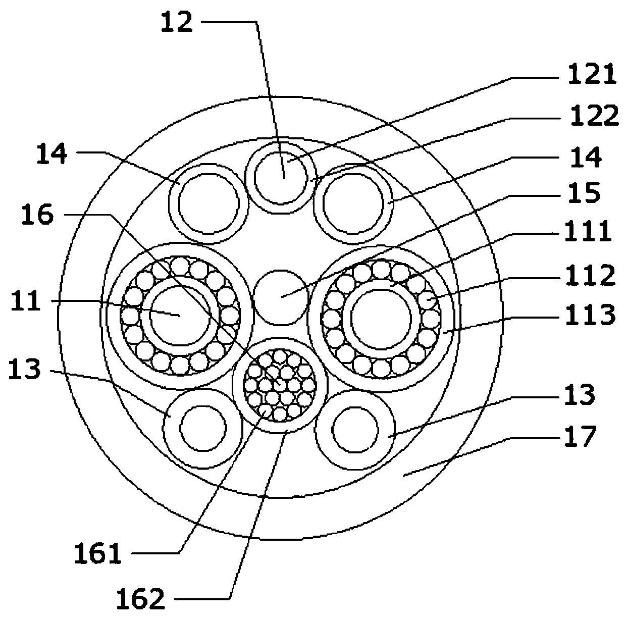
[0025] refer to Figure 1-3 , a high-current charging cable for electric vehicles, including at least one wire 112, the wire 112 is arranged in the cable 1, and at least includes a first inflow pipe 111 and an outflow pipe 14 for transmitting a cooling medium; the first inflow pipe 111 passes through the inside of the wire 112 , the first inflow pipe 111 is conductively connected to one end of the outflow pipe 14 at one end of the wire 112 , and the outflow pipe 14 is arranged adjacent to the wire 112 .

[0026] The high-current charging cable provided by the present invention has its own inflow cooling pipe and outflow cooling pipe. Compared with only one inflow cooling pipe, when the same amount of cooling medium is passed through, the present invention can realize secondary cooling, which greatly reduces the coolin...


PUM


Abstract

The invention discloses a high-current charging cable used for an electric vehicle. The high-current charging cable comprises at least one strand of wires, wherein the wires are arranged in the cable; the high-current charging cable also at least comprises a first inflow pipe used for conveying a cooling medium and at least one outflow pipe; each first inflow pipe is arranged in the corresponding wires in a penetration manner; the first inflow pipe is connected with one end of the corresponding outflow pipe at one ends of the corresponding wires in a conduction manner; and each outflow pipe is arranged close to the corresponding wires. The high-current charging cable has the beneficial effects as follows: the charging cable provided by the invention has a cooling pipeline, so that a good refrigerating effect is achieved; and a specially-manufactured hole-sleeve-structured adapter is adopted, so that the first inflow pipe is protected while the contact area between the adapter and the wires is enlarged, thereby greatly lowering the contact resistance of the adapter.

Description

technical field [0001] The invention relates to the field of charging cables, in particular to a high-current charging cable for electric vehicles. Background technique [0002] The long charging time of electric vehicles has always been one of the important factors restricting the development of the electric vehicle industry. At present, the DC charging pile with the largest power on the market is 150KW, the charging current is 250A, and the charging time is nearly 1 hour. Such a long charging time greatly affects the enthusiasm of users to use electric vehicles. In order to increase the charging speed of electric vehicles, it is necessary to further increase the charging current, which will cause severe heating of the cable. The conventional countermeasure adopted is to increase the section of the cable, but the section of the cable currently on the market is too large. If the section of the cable is increased, it will be difficult for the user to operate normally. Theref...

Claims


Application Information

Patent Timeline
Patent Type & Authority Patents(China)
IPC IPC(8): H01B7/42H01B7/32H01B9/00
CPCH01B7/324H01B7/423H01B7/425H01B9/00
Inventor 廖正勇胡光祥罗兰龚志超
Owner 深圳宝新电线电缆制造有限公司
Why Eureka
Try Eureka