Target material mounting structure, magnetron sputtering equipment and magnetron sputtering method

An installation structure and magnetron sputtering technology, applied in sputtering coating, metal material coating process, vacuum evaporation coating, etc., can solve the problems of poor heat dissipation and short target life, and achieve rapid cooling, Strong power, guarantee the effect of equipment safety

Active Publication Date: 2021-06-04
CHONGQING COLLEGE OF ELECTRONICS ENG
View PDF18 Cites 0 Cited by
  • Summary
  • Abstract
  • Description
  • Claims
  • Application Information

AI Technical Summary

Problems solved by technology

[0005] The technical problem to be solved by the present invention is: the poor heat dissipation of the target installation structure of the existing magnetron sputtering equipment leads to the short life of the target

Method used


Image

  • Target material mounting structure, magnetron sputtering equipment and magnetron sputtering method
  • Target material mounting structure, magnetron sputtering equipment and magnetron sputtering method

Examples


Embodiment 1

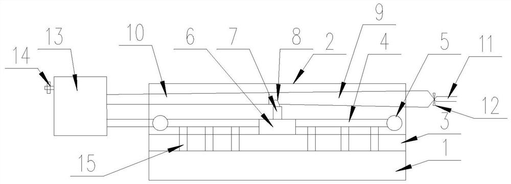
[0043] Such as figure 1 with figure 2 As shown, a target 1 installation structure includes a target 1 and a back plate 2, the target 1 is installed on one side of the back plate 2, and the feature is that a heat dissipation component is arranged inside the back plate 2, so The heat dissipation assembly includes a cooling water pipe and a suction assembly, the cooling water pipe is close to the target 1 side, the injection suction assembly is located away from the target 1, and the cooling water pipe is connected to the injection suction assembly.

[0044] The injection suction assembly includes an air pressure pipe 11, a ventilation pipe 9 and a drain pipe 10 connected in sequence, the ventilation pipe 9 communicates with one end of the injection suction pipe 8, and the other end of the injection suction pipe 8 is connected with the water suction pipe 7, so that The cooling water pipe is connected to the water suction pipe 7 , the drain pipe 10 is connected to a closed water...

Embodiment 2

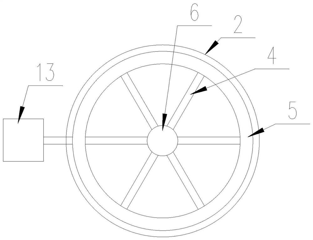
[0051] The difference between this embodiment and Embodiment 1 is that the back plate 2 is circular, and the cooling water pipe also includes a ring pipe 5, and the ring pipe 5 is annularly distributed inside the back plate 2, and the water collecting tank 6 is located in the ring shape of the ring pipe 5 , one end of the plurality of branch pipes 4 is connected to the ring pipe 5 , and the other end of the plurality of branch pipes 4 is connected to the water collecting tank 6 .

[0052] The branch pipes 4 are radially distributed inside the back plate 2 , and the water collecting tank 6 is arranged concentrically with the annular pipe 5 .

[0053] The annular pipe 5 is connected to a closed water tank 13, and a pressure relief valve 14 is arranged on the closed water tank 13.

[0054] The present invention connects the cooling water pipe and the drain pipe 10 of the injection suction assembly to the water tank, which can realize the recycling of cooling water. Since the high...

Embodiment 3

[0057] The difference between this embodiment and Embodiment 2 is that a pressure sensor is set on the airtight water tank 13, the pressure relief valve 14 is a solenoid valve, and the pressure sensor is used to detect the pressure in the airtight water tank 13 and transmit data For the PLC controller, the PLC controller controls the opening of the electromagnetic valve according to the data, so as to ensure that the pressure of the airtight water tank 13 does not exceed the threshold.


PUM


Abstract

The invention discloses a target material mounting structure, magnetron sputtering equipment and a magnetron sputtering method, and solves the technical problems of poor heat dissipation and short service life of an existing target material. The target material mounting structure comprises a target material and a back plate, wherein the target material is installed at one side of the back plate. The target material mounting structure is characterized in that a heat dissipation assembly is arranged in the back plate and comprises a cooling water pipe and an injection and suction assembly, the cooling water pipe is close to the side of the target material, the injection and suction assembly is located away from the target material, and the cooling water pipe is connected with the injection and suction assembly. The target material mounting structure has the advantages that the heat dissipation effect is good, the service life of the target material is long, and cooling water is not prone to falling into a vacuum cavity.

Description

technical field [0001] The invention relates to the field of coating technology, in particular to a target mounting structure and magnetron sputtering equipment. Background technique [0002] Magnetron sputtering is a type of physical vapor deposition (Physical Vapor Deposition, PVD). The general sputtering method can be used to prepare multiple materials such as metals, semiconductors, and insulators. [0003] The working principle of magnetron sputtering is: the working principle of magnetron sputtering is that electrons collide with argon atoms in the process of flying to the substrate under the action of electric field E, so that they are ionized to produce Ar positive ions and new Electrons; new electrons fly to the substrate, and Ar ions are accelerated to fly to the cathode target under the action of the electric field, and bombard the target surface with high energy to cause sputtering of the target. In sputtering particles, neutral target atoms or molecules are de...

Claims


Application Information

Patent Timeline
Patent Type & Authority Applications(China)
IPC IPC(8): C23C14/35
CPCC23C14/35C23C14/3407
Inventor 卢静
Owner CHONGQING COLLEGE OF ELECTRONICS ENG
Why Eureka
Try Eureka