Systems, devices, controllers, and methods for use in a floating production storage and offloading vessel

a technology for floating production storage and offloading, which is applied in the direction of waterborne vessels, hull parts, vessels, etc., can solve the problems of inability to meet the current or future conditions of the fpso vessel, the conventional approach to secure the fpso vessel is difficult, and requires a tremendous amount of preparation and planning

Active Publication Date: 2017-09-21
PTT EXPLORATION & PROD PUBLIC CO LTD
View PDF0 Cites 3 Cited by
  • Summary
  • Abstract
  • Description
  • Claims
  • Application Information

AI Technical Summary

Benefits of technology

[0006]In an exemplary embodiment, a turret system is described. The turret system may be for use in a floating production storage and offloading (FPSO) vessel. The FPSO vessel may include a hull and a moon pool opening in a bow section of the hull. The turret system may comprise a turret body and a transportable windlass subsystem. The turret body may be fixedly positionable in the moon pool opening and rotatable about a center axis defined by the moon pool opening. The turret body may include a top surface, a bottom surface opposite to the top surface, a first mooring line storage section, and a first mooring line channel section. The first mooring line storage section may include a first opening in the turret body top surface and a first cavity formed between the turret body top surface and turret body bottom surface. The first opening may operable to receive a first mooring line. The first cavity may be operable to house at least a majority length of the first mooring line. The first mooring line channel section may be formed through the turret body between the turret body top surface and turret body bottom surface. The first mooring line channel section may be an elongated passageway for the first mooring line to pass between an exterior of the FPSO vessel and the first mooring line storage section. The turret body may also include a second mooring line storage section and a second mooring line channel section. The second mooring line storage section may include a second opening in the turret body top surface and a second cavity formed between the turret body top surface and turret body bottom surface. The second opening may be operable to receive a second mooring line. The second cavity may be operable to house at least a majority length of the second mooring line. The second mooring line channel section may be formed through the turret body between the turret body top surface and turret body bottom surface. The second mooring line channel section may be an elongated passageway for the second mooring line to pass between an exterior of the FPSO vessel and the second mooring line storage section. The transportable windlass subsystem may include a rotatable member configurable to rotate in a first direction and a second direction opposite to the first direction. The transportable windlass system may be configured to be securable to and transportable between a plurality of locations on the turret body top surface, including a first location and a second location. The first location may be a location on the turret body top surface between the first mooring line channel section and the first opening of the first mooring line storage section. The second location may be a location on the turret body top surface between the second mooring line channel section and the second opening of the second mooring line storage section. The transportable windlass assembly may be configurable to receive and control a movement of a portion of the first mooring line between the first opening of the first mooring line storage section and the first mooring line channel section when the transportable windlass assembly is configured to be secured to the turret body top surface at the first location.
[0007]In another exemplary embodiment, a windlass assembly is disclosed. The windlass assembly may be for use in a turret system of a floating production storage and offloading (FPSO) vessel. The FPSO vessel may comprise a hull and a moon pool opening in a bow section of the hull. The turret system may comprise a turret body positioned in the moon pool opening and rotatable about a center axis defined by the moon pool opening. The turret body may comprise a top surface, a bottom surface opposite to the top surface, a mooring line storage section, and a mooring line channel section. The mooring line storage section may comprise a first opening in the turret body top surface and a first cavity formed between the turret body top surface and turret body bottom surface. The first opening may be operable to receive a mooring line. The mooring line channel section may be formed through the turret body between the turret body top surface and turret body bottom surface. The mooring line channel section may be an elongated passageway for the mooring line to pass between an exterior of the FPSO vessel and the mooring line storage section. The windlass assembly may comprise a transportable windlass subsystem. The transportable windlass subsystem may comprise a rotatable member configurable to rotate in a first direction and second direction opposite to the first direction. The transportable windlass subsystem may be configured to be securable to and transportable between a plurality of locations on the turret body top surface. When the transportable windlass assembly is configured to be secured to the turret body top surface at a first location between the first opening and the mooring line channel section, the transportable windlass assembly may be configurable to receive and control a movement of a portion of the mooring line between the first opening of the mooring line storage section and the mooring line channel section.

Problems solved by technology

It is recognized in the present disclosure that conventional approaches to securing an FPSO vessel relative to a location of a bottom of a body of water is difficult, time-consuming, and requires a tremendous amount of preparation and planning.
Furthermore, such planning and pre-calculations may not reflect the current or future conditions for the FPSO vessel, such as depth, tension requirements, length requirements of each mooring line, etc.

Method used


Image

  • Systems, devices, controllers, and methods for use in a floating production storage and offloading vessel
  • Systems, devices, controllers, and methods for use in a floating production storage and offloading vessel
  • Systems, devices, controllers, and methods for use in a floating production storage and offloading vessel

Examples


Embodiment Construction

[0028]It is recognized in the present disclosure that conventional approaches, systems, devices, and methods for use in securing an FPSO vessel relative to a location of a bottom of a body of water are difficult and time-consuming to perform, and also requires a tremendous amount of preparation, planning, measurements, and calculations. Furthermore, such planning and pre-calculations may not reflect the current and / or future conditions and / or requirements for the FPSO vessel, including requirements pertaining to depth, tension, and length of each of the plurality of mooring line, etc.

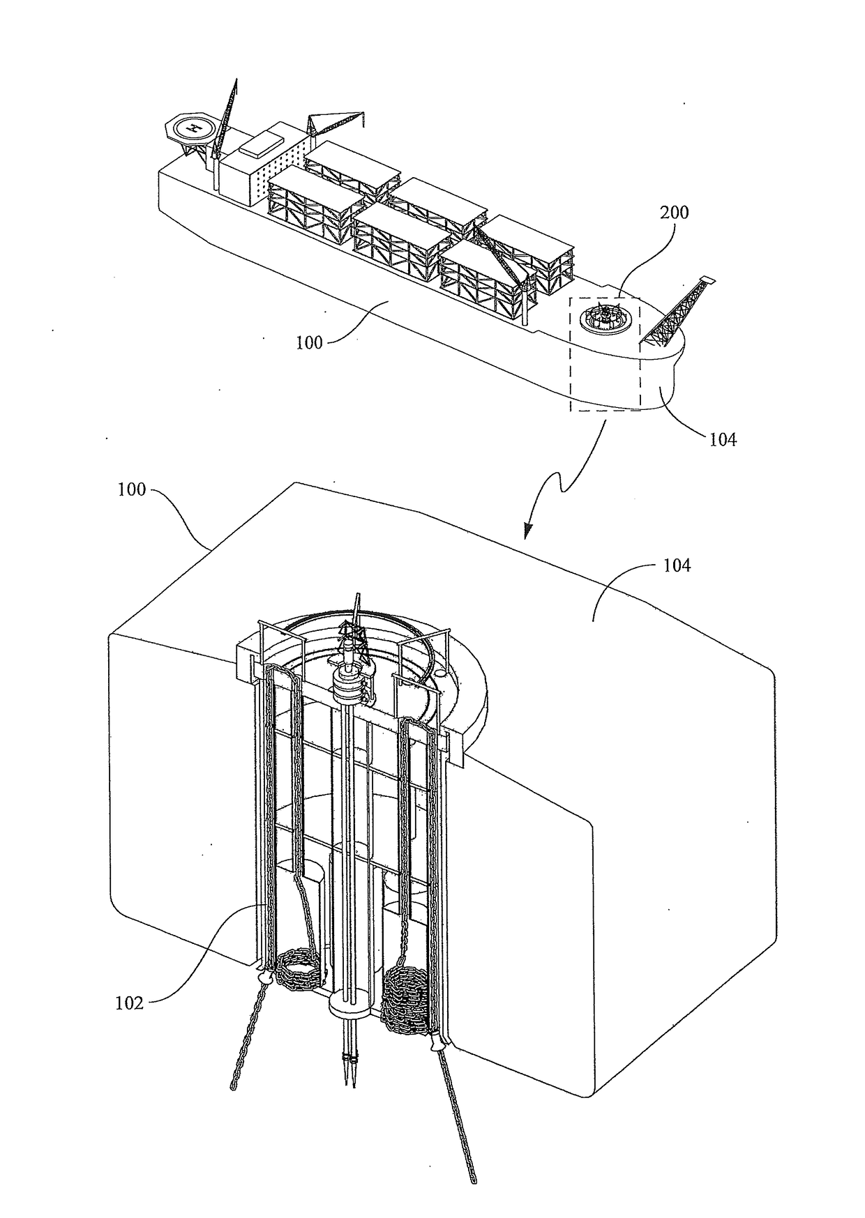
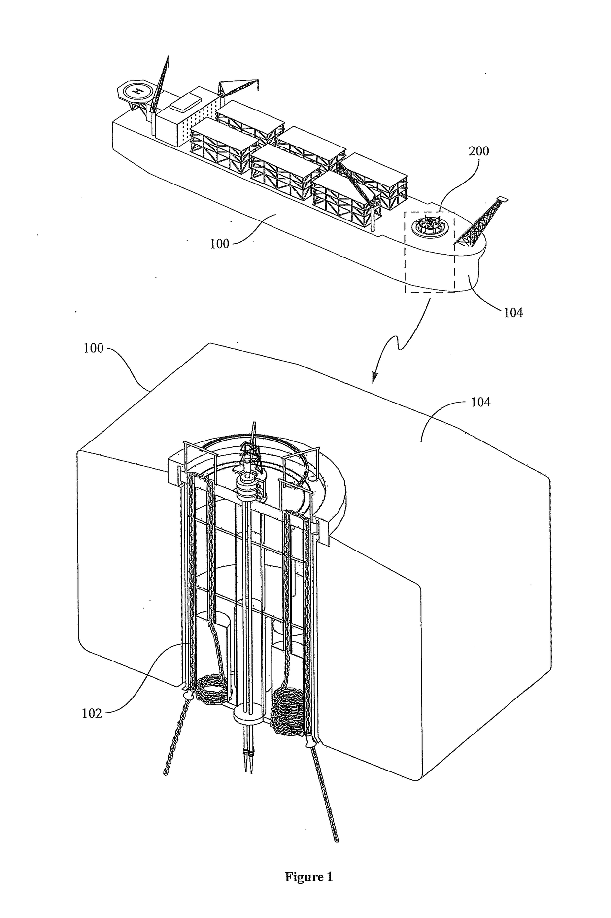
[0029]Present example embodiments relate generally to systems, subsystems, devices, controllers, and methods for use in, among other things, controlling and / or securing a position of a vessel relative to a bottom of a body of water.

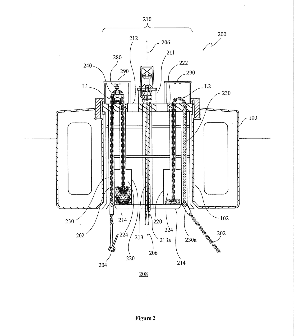
[0030]Example embodiments relate to and / or comprise a turret system, or the like. The turret system may include a turret body and a windlass subsystem. The turret body may in...


PUM


Abstract

Embodiments relate generally to a turret system for use in an FPSO vessel. The turret system may comprise a turret body and windlass subsystem. The turret system may comprise a top and bottom surface, first and second mooring line storage sections, and first and second mooring line channel sections. Each mooring line storage section may include an opening and cavity. Each opening is operable to receive a mooring line. Each mooring line channel section may be an elongated passageway for a mooring line to pass between an exterior of the FPSO vessel and a mooring line storage section. The windlass subsystem may comprise a rotatable member, and configured to be transportable between a plurality of locations. When the windlass assembly is configured to be secured to the turret body, the windlass assembly is configurable to control a movement of a mooring line.

Description

BACKGROUND[0001]The present disclosure relates generally to systems, devices, controllers, and methods for use in a floating production storage and offloading (FPSO) vessel, and more specifically, to turret systems and windlass assemblies for use in FPSO vessels.[0002]In general, a vessel, such as a floating production storage and offloading (FPSO) vessel, may be used to extract valuable hydrocarbons from a natural reservoir source located at a particular area under a bottom of a body of water (such as an ocean, sea, etc.). The extraction process may take several years for large reservoirs, and typically less time may be required for smaller (marginal) reservoirs.[0003]In order to perform the extracting of such hydrocarbons, the FPSO vessel is required to be securably positioned relative to a location on the bottom of the body of water. Due to the large size of FPSO vessels, this is generally achieved by using a plurality of mooring lines having anchors at its distal end. In prepara...

Claims


Application Information

Patent Timeline
Patent Type & Authority Applications(United States)
IPC IPC(8): B63B21/50B63B21/10
CPCB63B21/507B63B2035/448B63B2003/147B63B21/10B63B21/227
Inventor AIMCHAROENCHAIYAKUL, MANIT
Owner PTT EXPLORATION & PROD PUBLIC CO LTD
Why Eureka
Try Eureka