
Trippable Control System for a Breaker Pole and Breaker Gear

a control system and breaker gear technology, applied in the direction of protective switch operation/release mechanism, contact mechanism, protective switch details, etc., can solve the problem that the control system currently available is not suitable for ensuring

Active Publication Date: 2017-09-21
SOCOMEC
View PDF4 Cites 6 Cited by
  • Summary
  • Abstract
  • Description
  • Claims
  • Application Information

AI Technical Summary

Benefits of technology

The invention proposes a new control system that can reliably and quickly change the position of electrical breaker poles. This ensures the system operates efficiently and prevents malfunctions.

Problems solved by technology

The control systems that are presently available are not suitable for ensuring an automatic changeover from the closed position to the open position in reliable manner, in particular because they do not supply sufficient mechanical energy to enable electrical power breaker gear to be actuated, or they do not satisfy certain major safety criteria such as changing over independently of conditions of use or ensuring high speed for the changeover operation.

Method used


Image

  • Trippable Control System for a Breaker Pole and Breaker Gear
  • Trippable Control System for a Breaker Pole and Breaker Gear
  • Trippable Control System for a Breaker Pole and Breaker Gear

Examples


Embodiment Construction

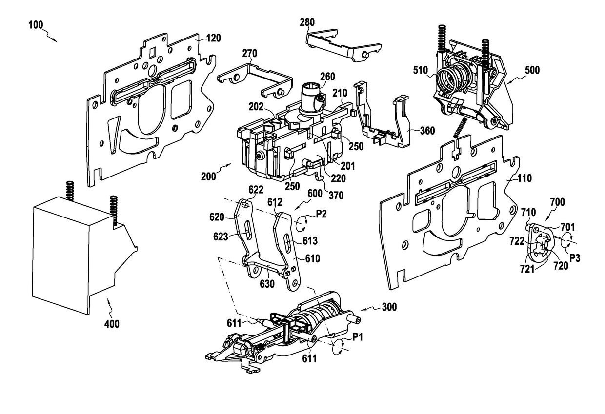
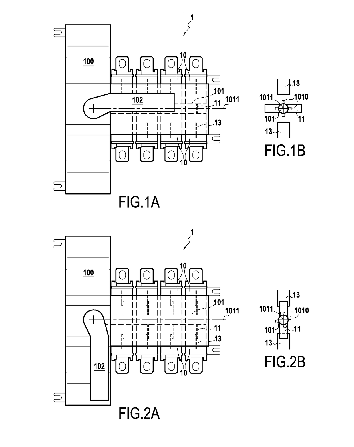
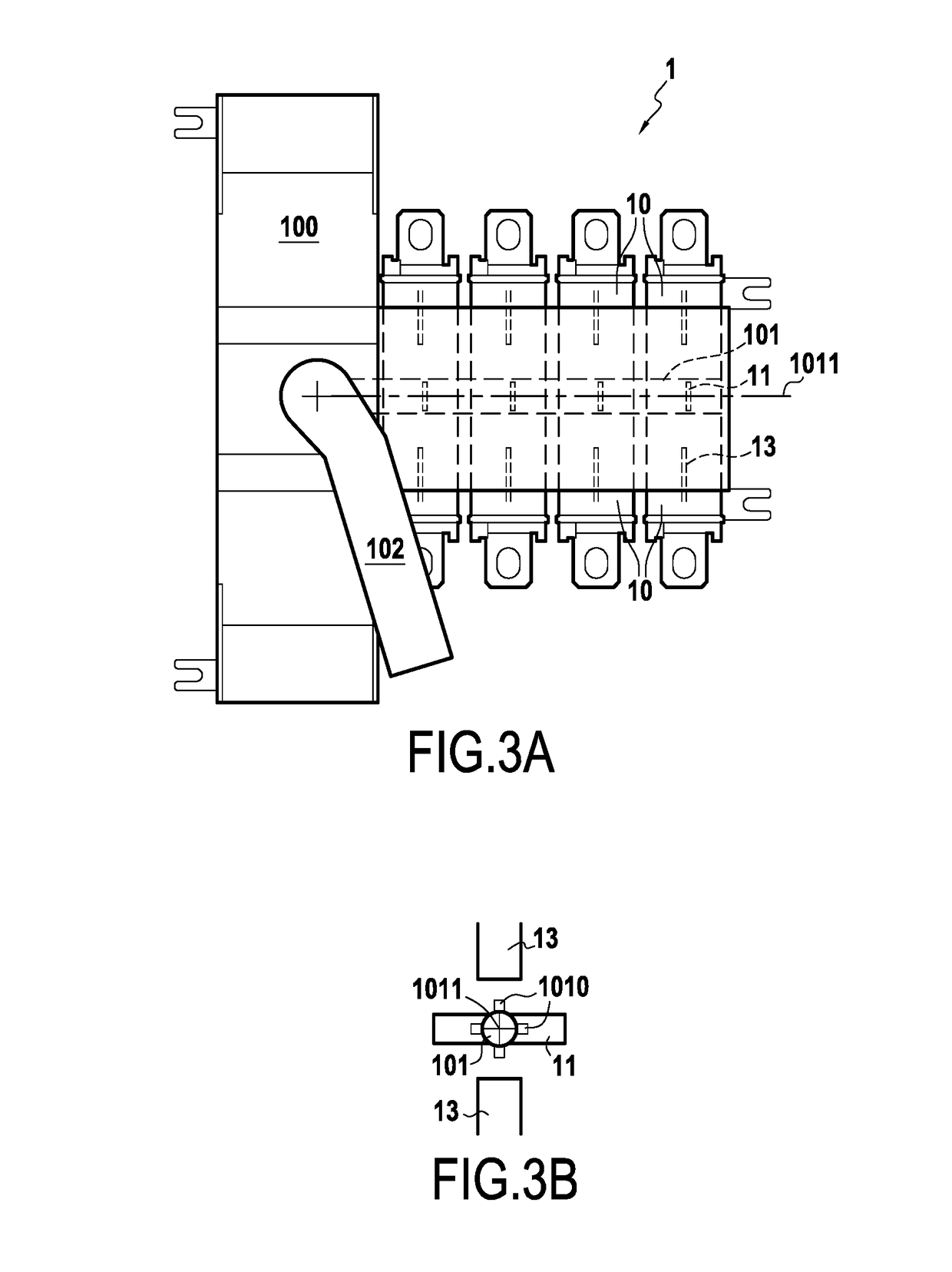
[0054]FIG. 1A shows breaker gear 1 in accordance with an embodiment of the invention. In the presently-described embodiment, the gear 1 comprises a trippable control system 100 in accordance with an embodiment, together with a plurality of breaker poles 10. The breaker poles 10 correspond to breaker devices such as interrupters, switches, or fused switch-disconnectors. As shown in FIGS. 1A and 1B, each breaker pole 10 is connected to the trippable control system 100 by a breaker shaft 101 that is secured firstly to a link of the system 100, as described in detail below, and secondly to each movable contactor of the breaker poles that correspond in this example to a set of movable contacts 11, the shaft 101 defining the axis of rotation for the movable contacts 11. When the shaft 101 is caused to turn by the system 100 that serves to move the movable contacts 11 of each breaker pole between an open position (FIG. 1A) in which the movable contacts 11 are placed at a distance from stat...


PUM


Abstract

A trippable control system for one or more electrical breaker poles, comprises a first link pivotable about a first pivot point between first and second positions; a second link pivotable about a pivot axis for connecting to one or more breaker poles, whereby movement of the first link causes the second link to pivot about the pivot axis between a position for opening and a position for closing the breaker pole(s); and a trip mechanism suitable for releasing the first pivot point and for exerting a movement force on the first link to move the first link between the second and third positions when the first link pivots about a second pivot point. Movement of the first link between the second and third positions causes the second link to pivot about the pivot axis between the position for closing the breaker pole(s) and the position for opening the breaker gear.

Description

BACKGROUND OF THE INVENTION[0001]The present invention relates to the general field of electrical breaker gear, and more particularly to systems enabling breaking to be actuated in this type of gear.[0002]This type of installation comprises one or more electrical breaker poles such as trippable switch-disconnectors, trippable fused switch-disconnectors, trippable switches, and circuit breakers. The main functions of such poles are the following:[0003]setting up and interrupting electric currents on load, on overload, and on short circuits;[0004]protecting a site and personnel against electrical risks; and[0005]guaranteeing user safety (actuation, lockout, and isolation).[0006]Electrical breaker gear is fitted with a control system connected to the electrical breaker poles and from which breaking of circuit breaking is controlled. The control system constitutes the most important safety element of the installation since it is the control system that determines the level of performanc...

Claims


Application Information

Patent Timeline
Patent Type & Authority Applications(United States)
IPC IPC(8): H01H21/30H01H21/36H01H71/10
CPCH01H21/30H01H2235/01H01H21/36H01H71/1009H01H1/22H01H3/58H01H71/527H01H71/56H01H83/12
Inventor DUMONT, ROGERMARCHAL, ARNAUDROGOSINSKI, DAMIEN
Owner SOCOMEC
Learn More