Steering column device

Inactive Publication Date: 2017-10-05
FUJI KIKO CO LTD
View PDF0 Cites 10 Cited by
  • Summary
  • Abstract
  • Description
  • Claims
  • Application Information

AI Technical Summary

Benefits of technology

[0007]However, even when the bush is disposed between the connection shaft and the laterally elongated hole of the middle bracket side, a gap is generated between the connection shaft and the laterally elongated hole of the middle bracket side, for allowing the relative movement at the telescopic adjustment. Moreover, this gap is generated in upward and downward directions which are identical to the tilt adjustment direction. Accordingly, th

Problems solved by technology

On the other hand, the connection shaft side of the middle bracket is not ti

Method used


Image

  • Steering column device
  • Steering column device
  • Steering column device

Examples


Embodiment Construction

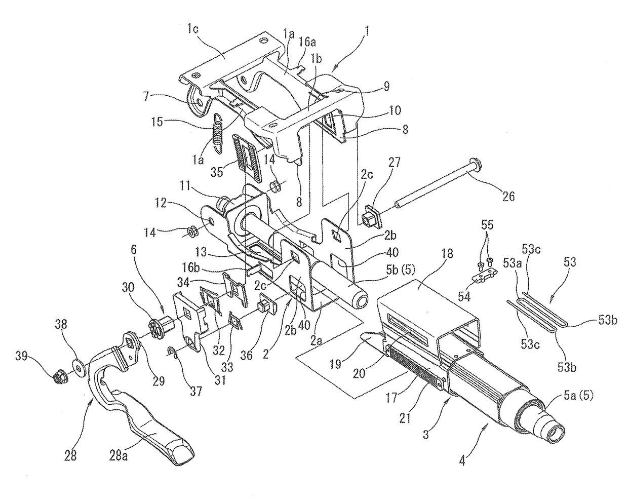
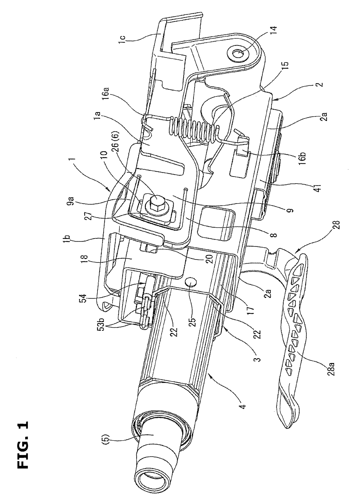
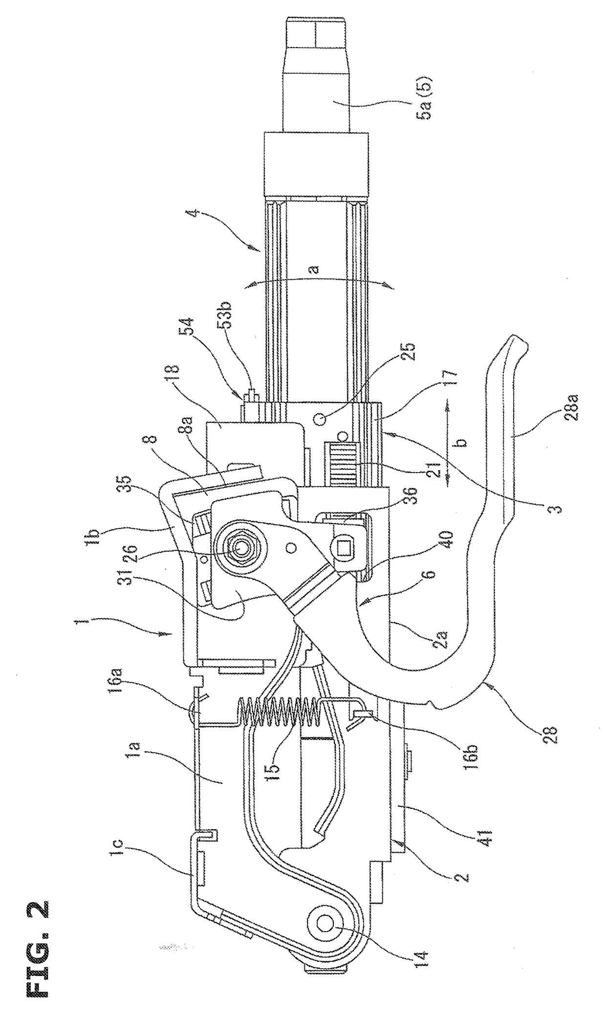
[0021]FIGS. 1 to 10 shows a steering column device according to a first embodiment of the present invention, which is arranged to perform a tilt operation and a telescopic operation.

[0022]FIG. 1 shows a perspective view showing an overall configuration of the steering column device. FIG. 2 is a side explanation view showing a left side of the steering column device shown in FIG. 1. FIG. 3 is a front explanation view showing the steering column device shown in FIG. 1. FIG. 4 is an overall sectional explanation view showing the steering column device shown in FIG. 2. FIG. 5 is an exploded perspective view showing constituting components of the steering column device shown in FIG. 1. Besides, in below explanations, a “front side”, a “rear side”, a “front end”, a “rear end”, “forward and rearward directions”, “upward and downward directions”, and so on are based on directions in a state where the steering column device is mounted on a vehicle. For example, the “front side” corresponds t...


PUM


Abstract

A steering column device includes: a steering column; and a the telescopic guide mechanism including a second telescopic elongated hole formed in one of the lower wall portion of the tilt bracket and the bottom wall portion of the steering column, and a sliding guide member which is provided to the other of the lower wall portion of the tilt bracket and the bottom wall portion of the steering column which does not include the second telescopic elongated hole, whose a portion confronts the second telescopic elongated hole, and which elastically sandwiches an edge portion of the second telescopic elongated hole in the upward and downward directions.

Description

BACKGROUND OF THE INVENTION[0001]The present invention relates to a steering column device, and more specifically to a steering column device having a tilt adjustment function and a telescopic adjustment function for adjusting a position of a steering wheel.[0002]U.S. Patent Application Publication No. 2009 / 066070 (corresponding to Japanese Patent No. 4567040) discloses a steering column device having a tilt adjustment function for adjusting a position of a steering wheel in upward and downward directions, and a telescopic adjustment function for adjusting the position of the steering wheel in forward and rearward directions.[0003]In general, in the tilt adjustment function (mechanism), the steering column is supported to be swung in the upward and downward directions about a tilt hinge pin provided to a front end side of the vehicle. The steering column device includes a vehicle body mounting bracket which is disposed to bridge the steering column, and which has side walls. The sid...

Claims


Application Information

Patent Timeline
IPC IPC(8): B62D1/189B62D1/19B62D1/184
CPCB62D1/189B62D1/195B62D1/184B62D1/19
Inventor MATSUNO, MITSUYOSHISAWAMURA, KOJISAKAMOTO, MASATOSHISHIMADA, AYAKATAKURA, REOITO, TADAO
Owner FUJI KIKO CO LTD
Why Eureka
Try Eureka