
Automatic false pupil contact lens

a contact lens and false pupil technology, applied in the field of electronic devices, can solve problems such as one or more vision problems, distortion of the field of vision,

Inactive Publication Date: 2017-10-05
INTEL CORP
View PDF4 Cites 3 Cited by
  • Summary
  • Abstract
  • Description
  • Claims
  • Application Information

AI Technical Summary

Problems solved by technology

By contrast, if a pupil opening is too small light rays may experience diffraction when they pass through the pupil, which distorts the field of vision.
Various factors such a

Method used


Image

  • Automatic false pupil contact lens
  • Automatic false pupil contact lens
  • Automatic false pupil contact lens

Examples


Embodiment Construction

[0011]Described herein are exemplary systems and methods to implement an automatic false pupil contact lens in accordance with some examples. In the following description, numerous specific details are set forth to provide a thorough understanding of various examples. However, it will be understood by those skilled in the art that the various examples may be practiced without the specific details. In other instances, well-known methods, procedures, components, and circuits have not been illustrated or described in detail so as not to obscure the particular examples.

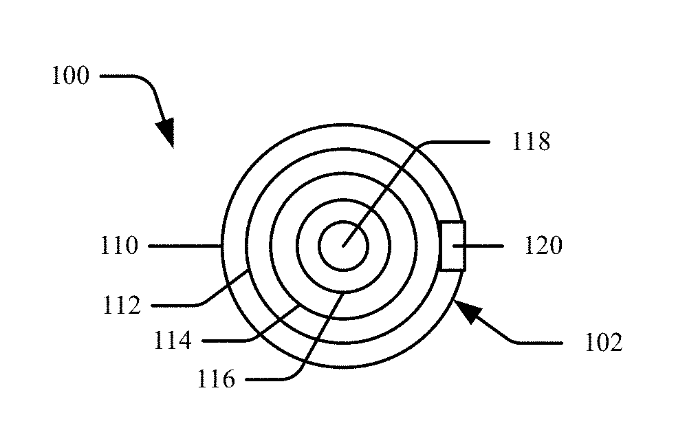
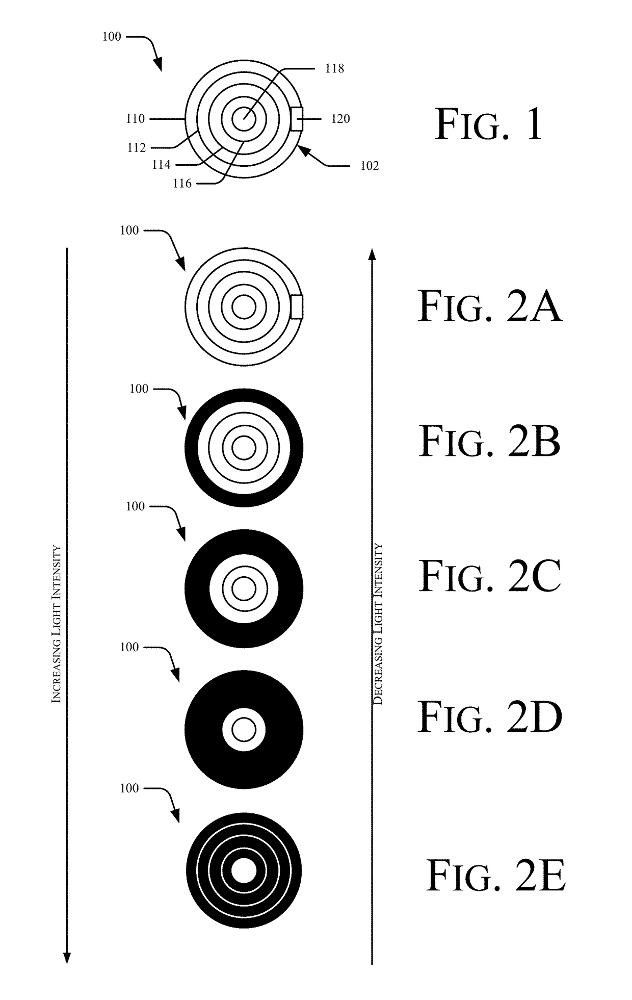
[0012]FIG. 1 is an illustration of an automatic false pupil contact lens in accordance with some examples. Referring to FIG. 1, in accordance with principles described herein, an automatic false pupil contact lens 100 comprises a body 102 formed from an optically translucent material and a coating on the body formed from at least one of a photochromatic material or an electrochromatic material that changes between a first...


PUM


Abstract

In one example an automatic false pupil contact lens comprises a body formed from an optically translucent material and a coating on the body formed from at least one of a photochromatic material or an electrochromatic material that, in response to an input, is to change between a first state in which the coating is optically translucent and a second state in which the coating is optically opaque in response to an input. Other examples may be described.

Description

BACKGROUND[0001]The subject matter described herein relates generally to the field of electronic devices and more particularly to an automatic false pupil contact lens.[0002]The size of an individual's pupil(s) impacts visual acuity, depth of field, and the ability to recognize objects. If a pupil opening is too large for a given ambient light level then the depth of field is reduced. By contrast, if a pupil opening is too small light rays may experience diffraction when they pass through the pupil, which distorts the field of vision.[0003]Various factors such as genetics, aging, and disease may cause an individual's pupil(s) to dilate in a less than ideal manner, which may result in one or more of the vision issues described above. Accordingly, an automatic false pupil contact lens may find utility, e.g., in managing eyesight issues caused by imperfect pupil dilation.BRIEF DESCRIPTION OF THE DRAWINGS[0004]The detailed description is described with reference to the accompanying figu...

Claims


Application Information

Patent Timeline
IPC IPC(8): G02C7/10G02C7/04
CPCG02C7/105G02C7/04G02C2202/16G02C7/102G02C2202/10G02C7/101
Inventor LEIP, TERRENCE P.
Owner INTEL CORP
Features
  • Generate Ideas
  • Intellectual Property
  • Life Sciences
  • Materials
  • Tech Scout
  • Unparalleled Data Quality
  • Higher Quality Content
  • 60% Fewer Hallucinations
Learn More