Optical waveguide and display device

a technology applied in the field of optical waveguides and display devices, can solve problems such as manufacturing challenges, and achieve the effect of reducing the likelihood of angular misalignmen

Active Publication Date: 2013-12-17
BAE SYSTEMS PLC
View PDF11 Cites 164 Cited by
  • Summary
  • Abstract
  • Description
  • Claims
  • Application Information

AI Technical Summary

Benefits of technology

[0015]Consequently, at least two of the gratings within the waveguide can be formed as a single grating, different parts of which are used for different diffraction operations. Alternatively they can be formed as two or three discrete gratings, all having the same orientation. Because their orientations are the same they effectively can be formed in one manufacturing operation, and thus the likelihood of angular misalignment is much reduced. We include such discrete but identical gratings within the term “single grating” in this specification.

Problems solved by technology

Whilst this arrangement is simpler than earlier proposals in which the third grating is in a separate waveguide from the first two, it still poses manufacturing challenges in that the three differently-oriented gratings (whether produced holographically or a surface-relief gratings) still must be very accurately aligned relative to each other if good results are to be achieved.

Method used


Image

  • Optical waveguide and display device
  • Optical waveguide and display device
  • Optical waveguide and display device

Examples


Embodiment Construction

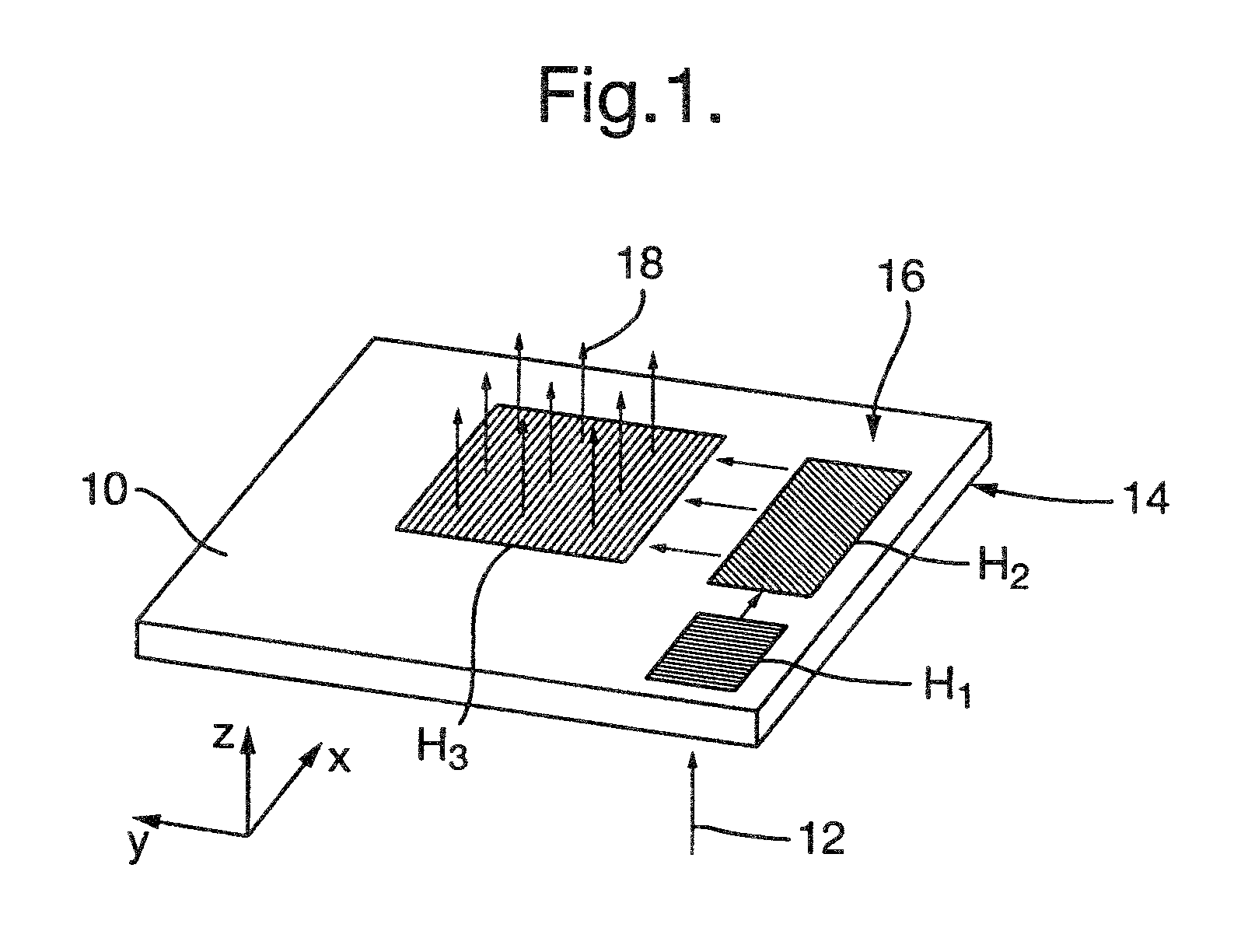
[0021]Referring to FIG. 1, a prior art slab waveguide 10 incorporates three separate differently-oriented gratings H1, H2, H3. Image-bearing light 12 is incident in the Z-direction on grating H1, the grooves or other diffracting structure of which is oriented in the y-direction. The grating turns the light through 90°, which then propagates between the parallel faces 14, 16 of the waveguide in the x-direction. The light then encounters grating H2, the diffracting structure of which is oriented at 45° to the x and y directions. This grating expands the image-bearing light in the x-dimension, turns it through 90° into the y direction and presents it to the grating H3, the diffracting structure of which is oriented in the x-direction. The grating expands the light in the y-dimension and releases in the z-direction as a two-dimensional image 18 visible to a observer. The preferred embodiments of the present invention now to be described achieve the same functionality in an alternative w...


PUM


Abstract

In a slab waveguide which expands an image-bearing pupil into a visible image, reflective edge surfaces are used to redirect once-diffracted light back through the same grating structure. The number of separate grating structures thereby can be reduced to two or even one, compared to three in the prior art.

Description

BACKGROUND OF THE INVENTION[0001]This invention relates to an optical waveguide and a display device. In particular it is relevant to display devices in which image bearing light is injected into a waveguide, is expanded in two orthogonal dimensions to form a visible image and is released from the waveguide.[0002]A prior art device of this type is shown in U.S. Pat. No. 6,509,529. In that device a slab waveguide contains three separate differently-oriented diffraction gratings, one to inject the light into the waveguide, a second to expand it in a first dimension, and a third to expand it in a second dimension and to release the thereby-formed image from the waveguide. Whilst this arrangement is simpler than earlier proposals in which the third grating is in a separate waveguide from the first two, it still poses manufacturing challenges in that the three differently-oriented gratings (whether produced holographically or a surface-relief gratings) still must be very accurately align...

Claims


Application Information

Patent Timeline
Patent Type & Authority Patents(United States)
IPC IPC(8): G02B27/14
CPCG02B27/0081G02B6/34G02B27/4272G02B27/4205
Inventor VALERA, MOHMED SALIMSIMMONDS, MICHAEL DAVID
Owner BAE SYSTEMS PLC
Why Eureka
Try Eureka