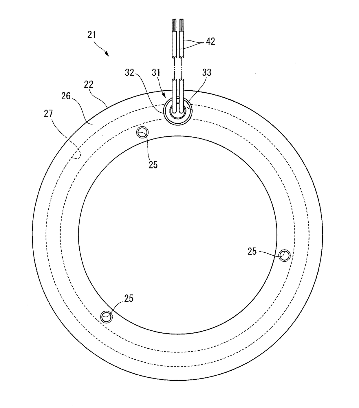
Seal structure for electromagnetic lead wire
- Summary
- Abstract
- Description
- Claims
- Application Information
AI Technical Summary
Benefits of technology
Problems solved by technology
Method used
Image
Examples
first embodiment
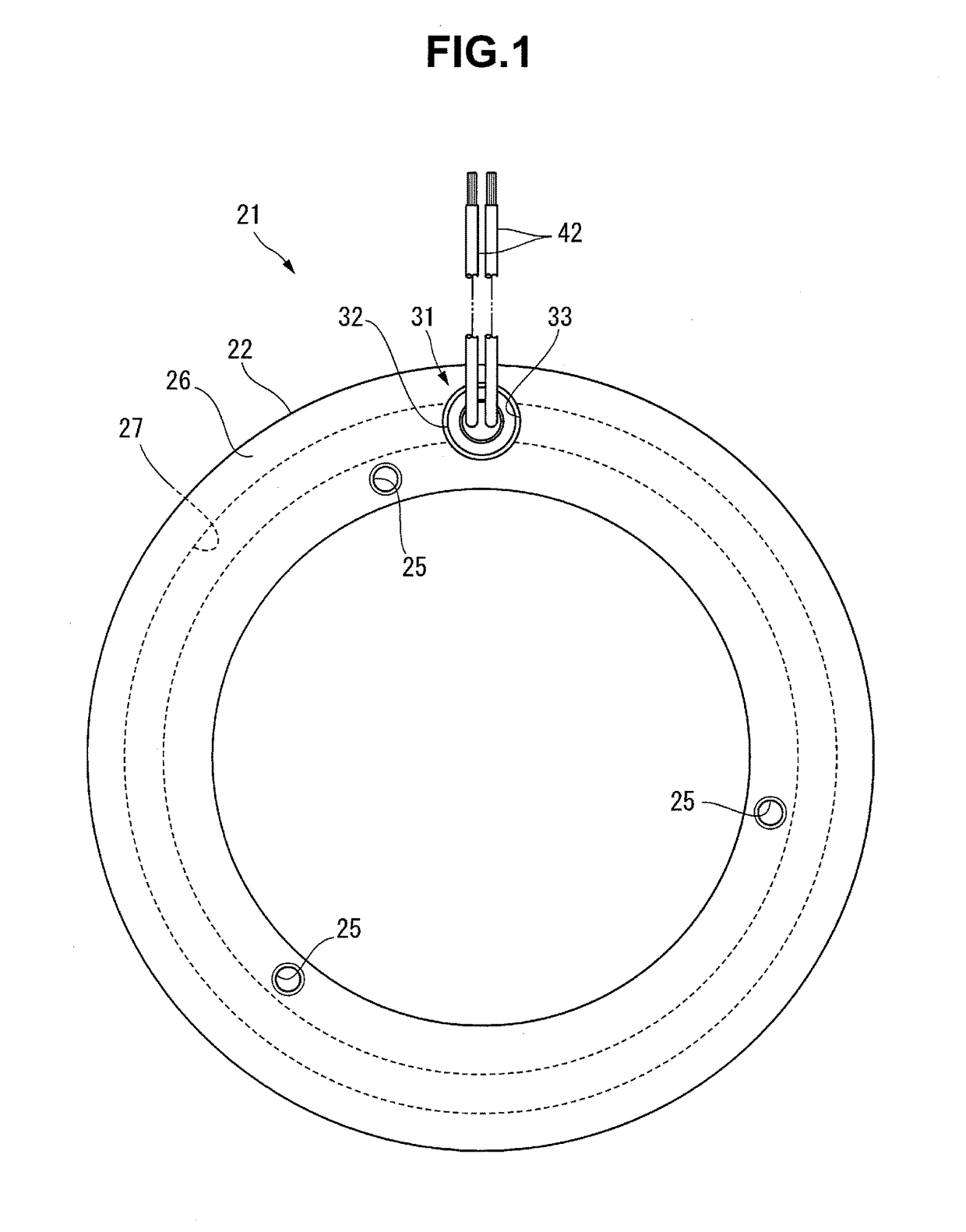
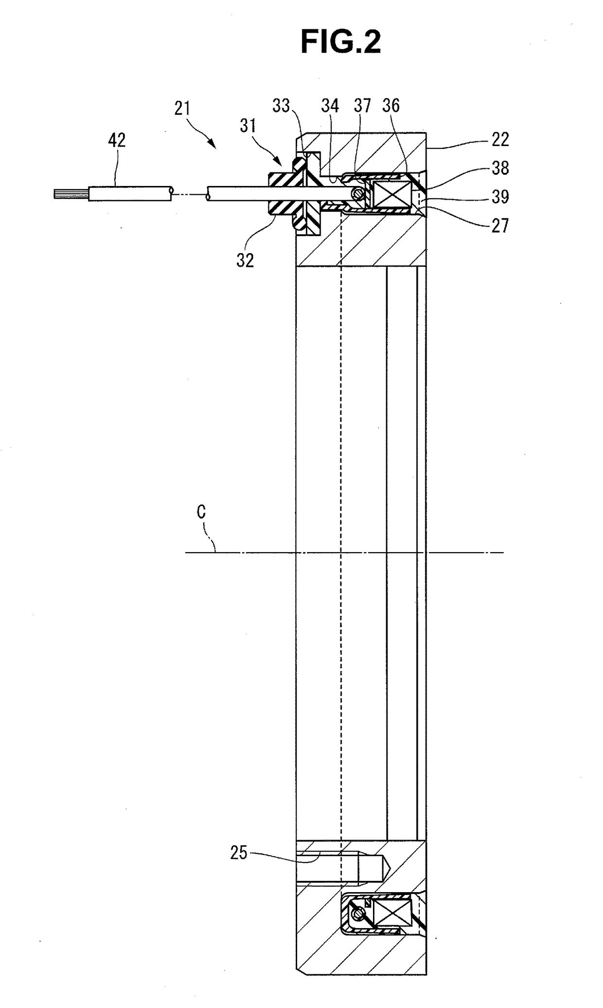
[0030]A seal structure for an electromagnet lead wire according to the first embodiment of the present invention will be described below in detail with reference to FIGS. 1 to 12.
[0031]An electromagnet 21 shown in FIG. 1 is formed by assembling components to be described later to an annular yoke 22. The electromagnet 21 according to this embodiment forms the field of a wet type electromagnetic clutch attached to a differential device (not shown) as a mechanical device. As shown in FIG. 12, the electromagnet 21 is used in a state in which one end of the yoke 22 in the axial direction (the left-and-right direction in FIG. 12) is attached to a case 24 of a mechanical device 23. The yoke 22 is fixed on a device inner surface 24a of the case 24. In the mechanical device 23, a lubricating oil is supplied into the device, although not illustrated. The electromagnet 21 is placed in an environment where the oil scatters in the mechanical device 23. Bolts (not shown) used to attach the electr...
second embodiment
[0055]A seal structure for an electromagnet lead wire according to the second embodiment of the present invention is configured as shown in FIG. 13. The same reference numerals as in FIGS. 1 to 12 denote the same or similar members in FIG. 13, and a detailed description thereof will appropriately be omitted. A seal structure 71 for an electromagnet lead wire shown in FIG. 13 is different from the seal structure 31 described in the first embodiment only in a projecting portion 56 of an insulating resin 39, and the rest of the structure is the same.
[0056]The projecting portion 56 of the insulating resin 39 according to this embodiment is provided with a cylinder 72 serving as a “standing portion” extending from the outer edge of a distal end face 56a in the axial direction of a yoke 22. The inner surface (the hole wall surface of a second hole portion extending in the axial direction) of a concave portion 33 of the yoke 22 is covered with the cylinder 72. The cylinder 72 is molded int...
third embodiment
[0059]A seal structure for an electromagnet lead wire according to the third embodiment of the present invention is configured as shown in FIG. 14. The same reference numerals as in FIGS. 1 to 12 denote the same or similar members in FIG. 14, and a detailed description thereof will appropriately be omitted. A seal structure 81 for an electromagnet lead wire according to this embodiment can be implemented without using the constituent members of a mechanical device 23.
[0060]In this embodiment, a through hole 82 and a concave portion 83 are formed in an annular wall 26 that forms the bottom of a coil storage groove 27. The through hole 82 extends in the axial direction of a yoke 22 and opens to the outer surface of the yoke 22 and a bottom surface 83a of the concave portion 83. The hole diameter of the through hole 82 allows a columnar portion 61 of a seal member 32 to be press-fitted. The concave portion 83 opens to the bottom of the coil storage groove 27. The hole diameter of the c...
PUM
 Abstract
Description
Claims
Application Information
 - R&D
- Intellectual Property
- Life Sciences
- Materials
- Tech Scout
- Unparalleled Data Quality
- Higher Quality Content
- 60% Fewer Hallucinations
Browse by: Latest US Patents, China's latest patents, Technical Efficacy Thesaurus, Application Domain, Technology Topic, Popular Technical Reports.
© 2025 PatSnap. All rights reserved.Legal|Privacy policy|Modern Slavery Act Transparency Statement|Sitemap|About US| Contact US: help@patsnap.com


