
Coreless Seal and Rolling Bearing

Active Publication Date: 2009-06-18
NTN CORP +1
View PDF6 Cites 3 Cited by
  • Summary
  • Abstract
  • Description
  • Claims
  • Application Information

AI Technical Summary

Benefits of technology

[0014]It is an object of the present invention to provide a coreless seal and a rolling bearing having high sealing properties even at low temperature.
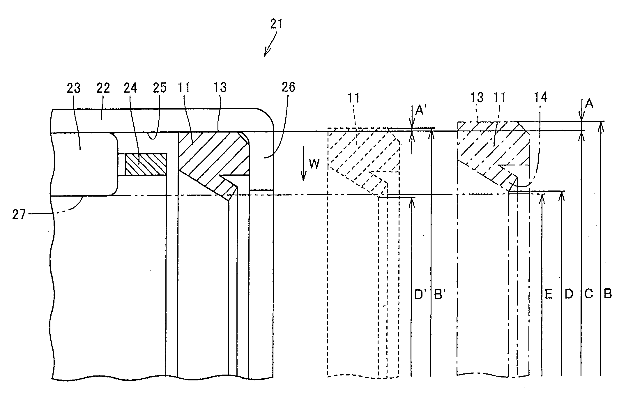
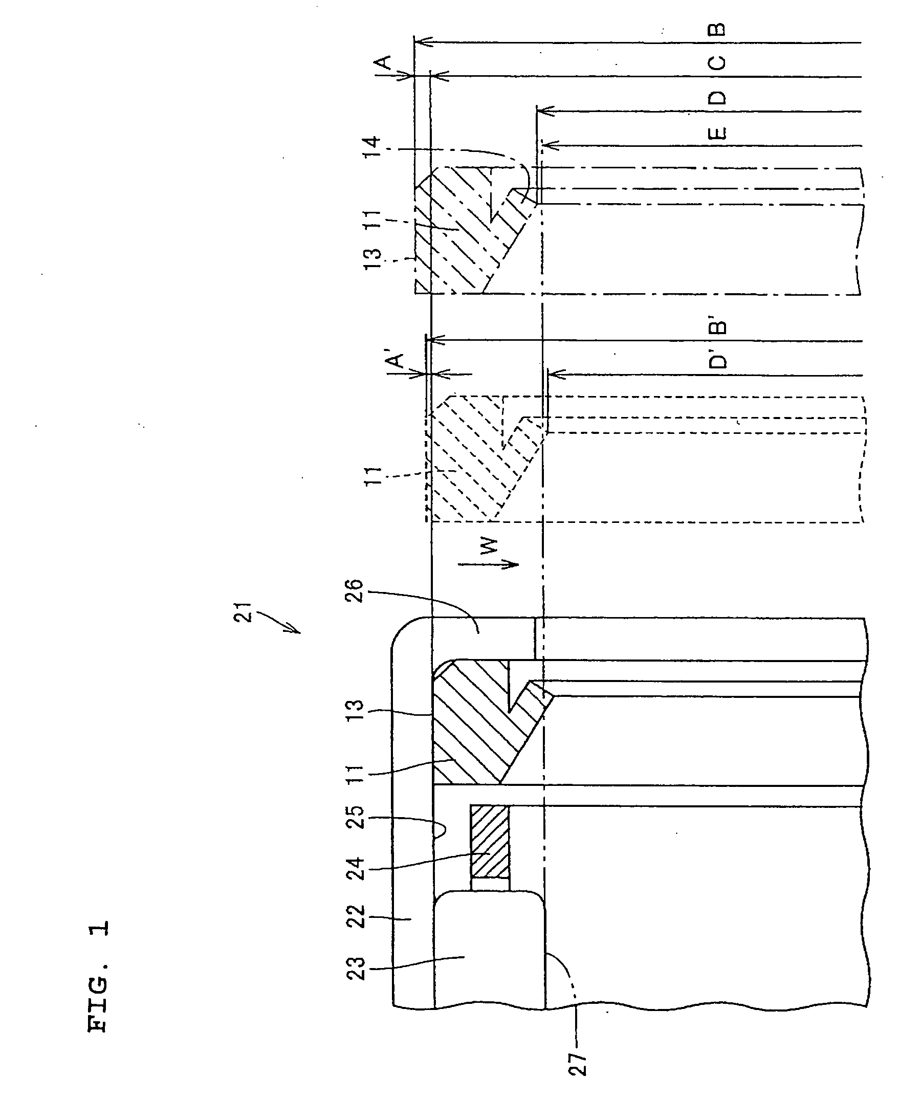
[0015]A coreless seal according to the present invention is arranged between a rotation shaft and an outer member having an inner diameter surface opposed to an outer diameter surface of the rotation shaft with a space to prevent leakage of fluid. Here, an outer diameter of the coreless seal is a dimension obtained by adding interference for an amount of thermal shrinkage.
[0016]According to the above constitution, even when the coreless seal positioned in the space between the rotation shaft and the outer member thermally shrinks and its outer diameter is reduced at low temperature, the outer diameter dimension of the coreless seal is larger than the inner diameter dimension of the inner diameter surface of the outer member, no gap is generated between the outer diameter surface of the coreless seal and the inner diameter surface of the outer member. Therefore, even at low temperature, the outer diameter surface of the coreless seal nip the inner diameter surface of the outer member with appropriate pressure, so that high sealing properties are provided.

Problems solved by technology

However, since the cored seal 101 for being assembled in the shell-type roller bearing comprises a plurality of members, its cost becomes high.
In addition, since the cored seal 101 for being assembled in the shell-type roller bearing has rigidity, it is difficult to remove it after assembled in the shell-type roller bearing.
However, the coreless seal 106 for being assembled in the shell-type roller bearing does not have the above dimensional relation at low temperature, so that leakage between them cannot be prevented.

Method used


Image

  • Coreless Seal and Rolling Bearing
  • Coreless Seal and Rolling Bearing
  • Coreless Seal and Rolling Bearing

Examples


Embodiment Construction

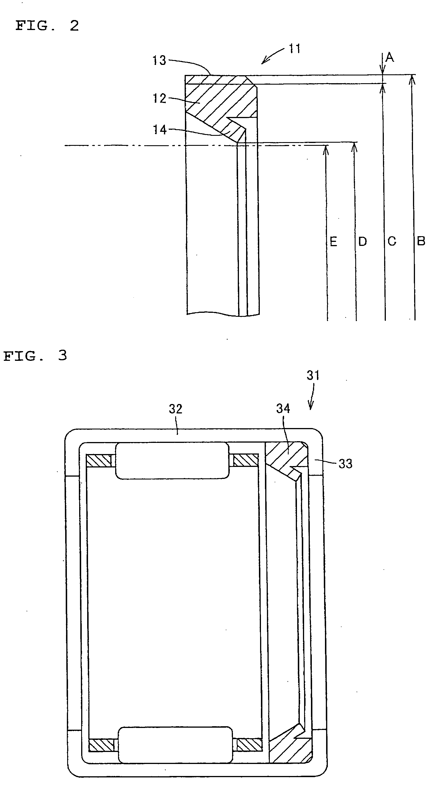
[0035]An embodiment of the present invention will be described with reference to the drawings hereinafter. FIG. 2 is a sectional view showing a part of a coreless seal according to one embodiment of the present invention as a coreless seal for being assembled in a shell-type roller bearing, in a free state at room temperature. Referring to FIG. 2, a coreless seal 11 for being assembled in a shell-type roller bearing only comprises an elastic annular member 12. An outer diameter B of the coreless seal 11 for being assembled in the shell-type roller bearing is a dimension obtained by adding interference 2A for an amount of thermal shrinkage to an inner diameter C of a shell-type outer ring serving as an outer member. In addition, an inner diameter D of the coreless seal 11 for being assembled in the shell-type roller bearing in which a lip part 14 projects toward the inner diameter is designed so as to be a little larger than an outer diameter E of a rotation shaft (not shown) support...


PUM


Abstract

A coreless seal 11 for being assembled in a shell-type roller bearing provided in a shell-type roller bearing comprises an elastic annular member 12. An outer diameter B of the coreless seal 11 for being assembled in the shell-type roller bearing is a dimension provided by adding interference 2A for an amount of thermal shrinkage to an inner diameter C of a shell-type outer ring. Since the annular member 12 shrinks in a direction shown by an arrow W at low temperature, the outer diameter of the coreless seal 11 for being assembled in the shell-type roller bearing is reduced from B to B′. However, since the outer diameter B is provided with the dimension A obtained by adding interference for an amount of thermal shrinkage, the coreless seal 11 for being assembled in the shell-type roller bearing has interference A′ in its outer diameter B′ even after the shrinkage.

Description

TECHNICAL FIELD[0001]The present invention relates to a coreless seal and a rolling bearing and more particularly, to a coreless seal and a rolling bearing used at low temperature.BACKGROUND ART[0002]A device to control air inflow to an engine of a car and the like includes a throttle valve device. FIG. 6 is a schematic view showing one example of the throttle valve device. Referring to FIG. 6, a throttle valve device 91 comprises a throttle body 94 forming an air inlet path in its inside, a throttle blade 95 adjusting an air inlet amount by opening and closing, a throttle shaft 93 to fix the throttle blade 95, and a shell-type roller bearing 92 to support the throttle shaft 93 rotatably. Here, the shell-type roller bearing 92 is used as a bearing to support the throttle shaft 93 because an outer diameter of the bearing is smaller than that of a ball bearing and the like, and a seal having high sealing properties can be assembled in, so that it has air leak protection performance.[0...

Claims


Application Information

Patent Timeline
IPC IPC(8): F16C33/76F16J15/32
CPCF16C19/466F16J15/32F16C33/7809
Inventor AKAMATSU, HIDEKINAKAGAWA, KENJI
Owner NTN CORP
Learn More