Apparatus for creating a swirling flow of fluid
Active Publication Date: 2017-10-12
YAOVAPHANKUL LUXNARA
View PDF17 Cites 0 Cited by
- Summary
- Abstract
- Description
- Claims
- Application Information
AI Technical Summary
Benefits of technology
The patent describes a device that helps to create a smooth and smooth flow of fluid within a transmission base. This is accomplished through the use of two holes and a curved surface. The first hole allows fluid to enter the device, while the curved surface helps to guide the fluid along a specific path within the device. This results in a laminar flow, which increases the flow speed and reduces any turbulence within the device. Overall, the device helps to create a more efficient and smooth fluid transfer.
Problems solved by technology
It is unable to increase the acceleration of swirling flow along the longitudinal internal cavity of the transmission base.
Method used
View moreImage
Smart ImageViewing Examples
Examples
Embodiment Construction
[0021]As the same as mention in Disclosure of Invention.
Login to View More PUM
 Abstract
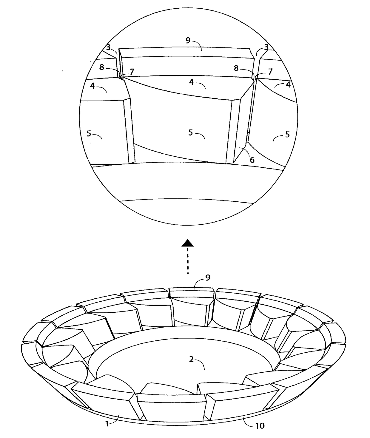
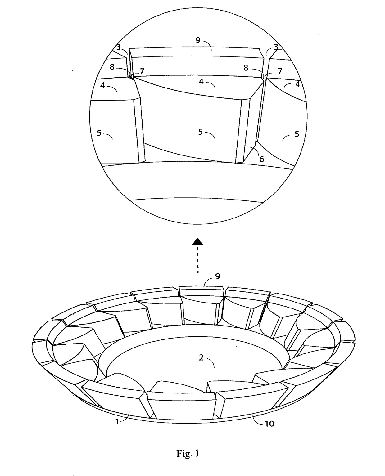
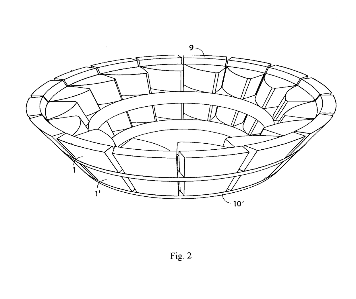
Apparatus or creating a swirling flow of fluid comprises a transmission base with an internal cavity to receive the fluid flow from outside via a side penetrable hole which the longitudinal inner surface of the transmission base will be in shape of slope of continuous line, or slope of line intervals with different degree of slope, or slope of line intervals with at least one bending angle or slope of curve either convex curve or concave curve with at least one curvature to increase or decrease acceleration of swirling flow along the longitudinal internal cavity and in the manner of a laminar swirling flow. And beside the side penetrable hole will become a side hole edge for regulating the flow of fluid to flow inside the transmission base in the manner of a laminar swirling flow in the internal cavity of transmission base which a part of the hole side edge can have an elevated insert shoulder for stacking the attachment to overlay on the insert supporting shoulder of another transmission base stack them higher.
Description
TECHNICAL FIELD[0001]Engineering related to the apparatus for creating a swirling flow of fluidBACKGROUND ART[0002]Reference is made to Thai patent number 41173 which discloses an apparatus for creating a swirling flow of fluid comprises a transmission base with an internal cavity to receive the fluid flow from outside via side penetrable hole where a hole side edge is formed. Where in the beginning section of convex curve of the hole side edge has to be the surface with a smallest angle of deviation of the emerging axis of the said penetrable hole, and the said hole side edge has to be the nearest surface to emerging axis of the side penetrable hole to deflect the flow of incoming fluid to the internal cavity of transmission base to flow attaching to the convex curve. It will induce the fluid in the internal cavity to flow to the convex curve resulting in Coanda Effect phenomena, said Coanda Effect will create a laminar flow of fluid along the same plane as an internal surface of t...
Claims
Login to View More Application Information
Patent Timeline
 IPC IPC(8): F15D1/00
CPCF15D1/0015
Inventor YOAVAPHANKUL, METHA
Owner YAOVAPHANKUL LUXNARA
Features
- R&D
- Intellectual Property
- Life Sciences
- Materials
- Tech Scout
- Unparalleled Data Quality
- Higher Quality Content
- 60% Fewer Hallucinations
Learn More Browse by: Latest US Patents, China's latest patents, Technical Efficacy Thesaurus, Application Domain, Technology Topic, Popular Technical Reports.
© 2025 PatSnap. All rights reserved.Legal|Privacy policy|Modern Slavery Act Transparency Statement|Sitemap|About US| Contact US: help@patsnap.com


