
Magnetic head slider having contacted portion at air outflow end side

a magnetic head slider and contact portion technology, applied in the direction of maintaining the head carrier alignment, recording information storage, instruments, etc., can solve the problems of unstable flying height, achieve the effect of reducing air density, reducing air density, and changing flying heigh

Inactive Publication Date: 2007-03-01
TDK CORPARATION
View PDF5 Cites 21 Cited by
  • Summary
  • Abstract
  • Description
  • Claims
  • Application Information

AI Technical Summary

Benefits of technology

The patent describes a magnetic head slider that reduces changes in flying height caused by changes in air pressure. The slider has a first flow path with a contracted portion that reduces flow velocity and creates positive pressure. The slider also has air-inflow-end-side protrusion surfaces that help reduce flying height. The bottom surface of the slider has a groove that acts as a negative pressure producing surface. The slider also has rail surfaces that connect the magnetic element surrounding surface and the air-inflow-end-side protrusion surfaces. The size of the slider and the position of the contracted portion can also affect flying height. Overall, the patent describes a design that effectively reduces changes in flying height caused by changes in air pressure.

Problems solved by technology

However, the flying height tends to become unstable due to a change in air pressure or a reduction in an air inflow amount resulting from, for example, a reduction in peripheral speed caused by size reduction of a magnetic disc.

Method used


Image

  • Magnetic head slider having contacted portion at air outflow end side
  • Magnetic head slider having contacted portion at air outflow end side
  • Magnetic head slider having contacted portion at air outflow end side

Examples


examples

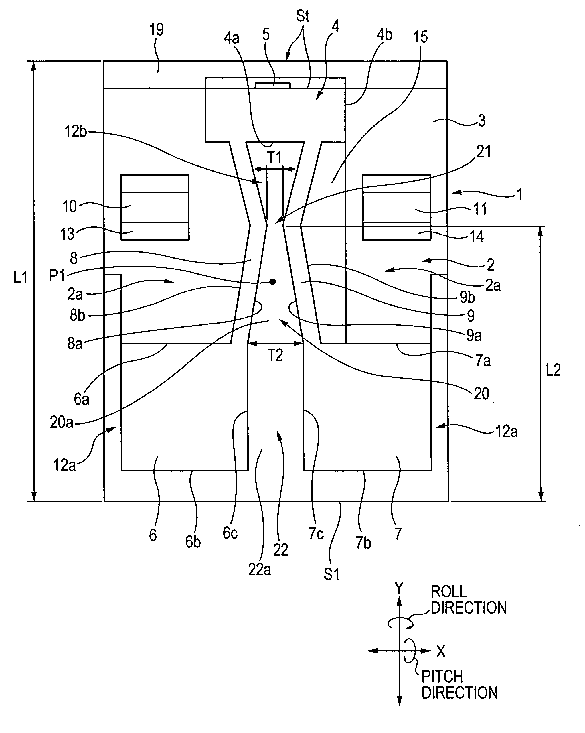
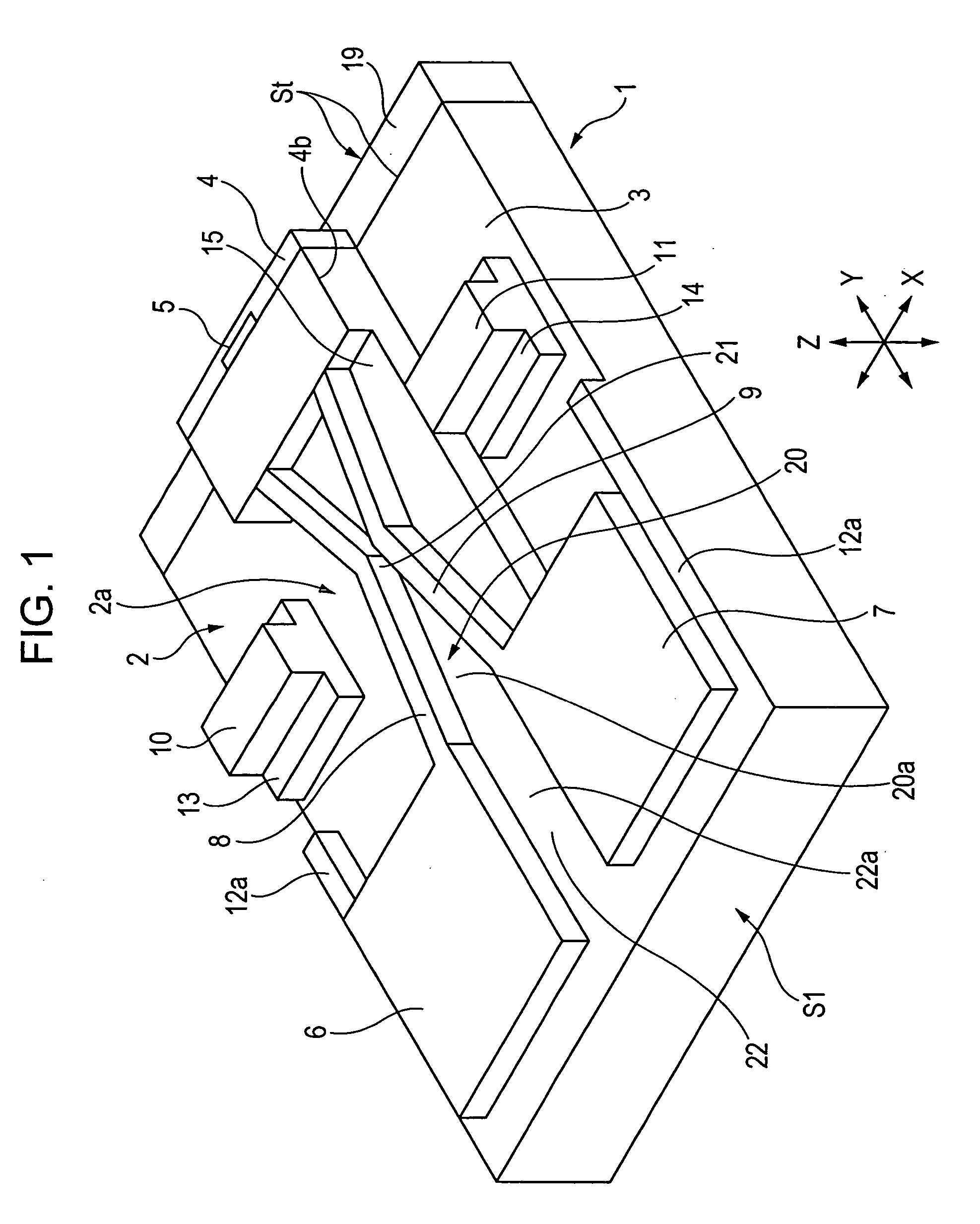
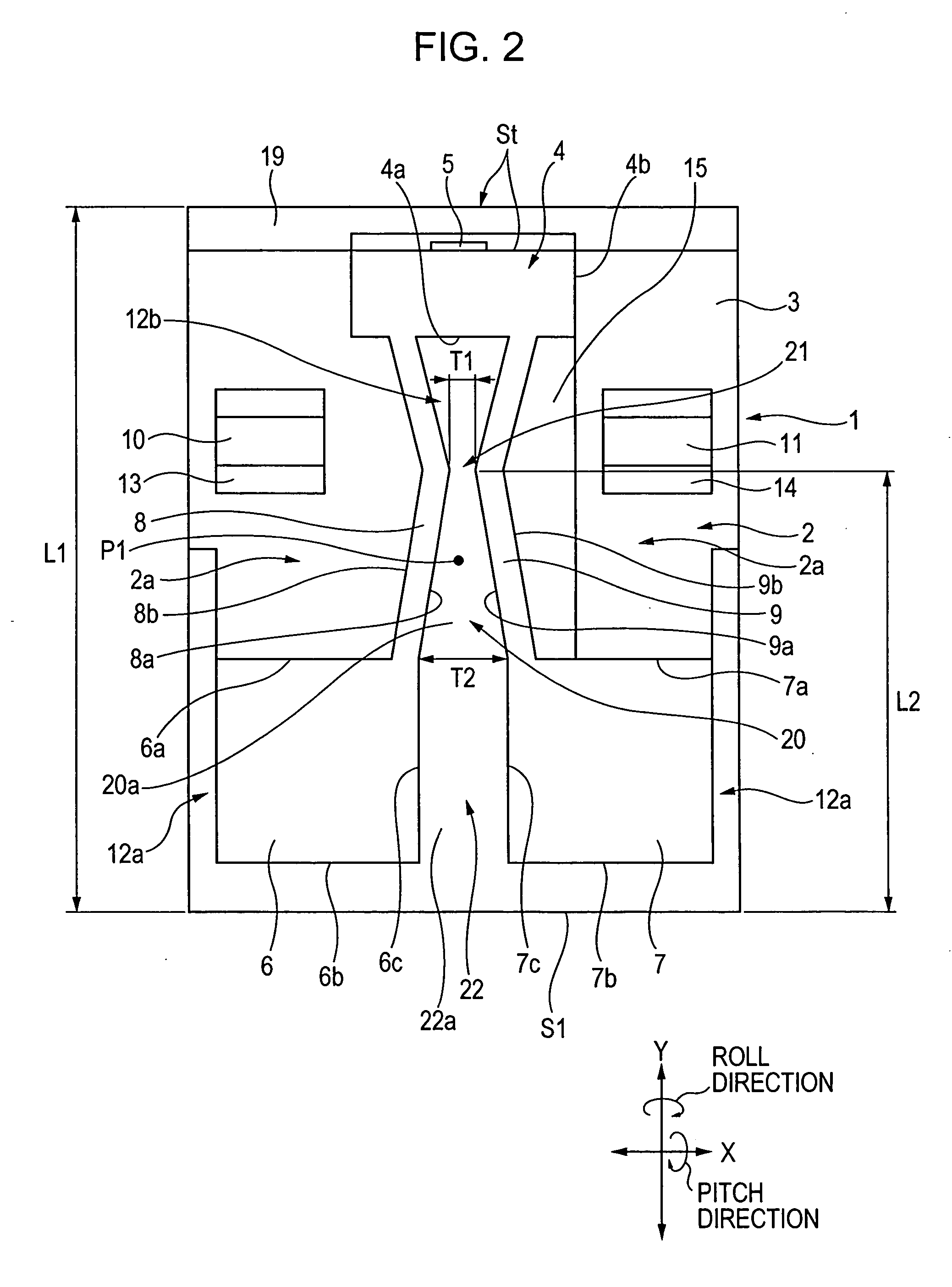
[0068] A plurality of magnetic head sliders having the form shown in FIGS. 1 and 2 were produced.

[0069] The magnetic head sliders have different widths T1 and T2 as shown in Table 1 below. The width T1 is that of the contracted portion 21 at the first flow path 20 formed between the rail surfaces 8 and 9, and the width T2 is that of the leading-side end of the first flow path 20.

[0070] Flying heights of the magnetic head sliders under air pressure at a flatland at sea level (0 meters) and flying heights of the magnetic head sliders under air pressure at a highland at 3048 meters above sea level were measured. The relationship between T1 / T2 of each magnetic head slider and height difference sensitivity was determined. The height difference sensitivity is equal to (flying height of magnetic head slider at a highland / flying height of magnetic head slider at a flatland)×100%. The experimental results are shown in Table 1 and FIG. 9.

TABLE 1LEADING-SIDECONTRACTEDHEIGHTWIDTH T2PORTIOND...


PUM

PropertyMeasurementUnit
depthaaaaaaaaaa
flying heightsaaaaaaaaaa
lengths L1aaaaaaaaaa

Abstract

A magnetic head slider is provided. The magnetic head slider has a leading-side protrusion surface and a protruding magnetic element surrounding surface disposed at a surface of a slider opposing a disc. A first flow path that has the form of a groove is disposed between the magnetic element surrounding surface and the leading-side protrusion surface. A contracted portion is provided in the first flow path so as to be positioned closer to a trailing side compared to a swing fulcrum of the slider.

Description

[0001] This application claims the benefit of Japanese Patent Application 2005-251104 filed on Aug. 31, 2005 which is hereby incorporated by reference. BACKGROUND [0002] 1. FIELD [0003] A magnetic head slider having a magnetic element that performs a recording operation and / or reproducing operation on a magnetic disc is provided. Related Art [0004] A disc-opposing surface of a magnetic head slider ordinarily has a groove and a protruding surface. The groove is disposed at the lowest position of the disc-opposing surface and is used to produce negative pressure. The protruding surface is used to produce positive pressure. A flying height of the magnetic head slider has been stabilized by, for example, forming the groove and the protruding surface with a suitable shape or setting the ratio between the areas of the groove and the protruding surface that they occupy at the disc-opposing surface to a proper ratio. [0005] However, the flying height tends to become unstable due to a change...

Claims


Application Information

Patent Timeline
Patent Type & Authority Applications(United States)
IPC IPC(8): G11B5/60
CPCG11B5/60
Inventor MATSUMOTO, TSUYOSHI
Owner TDK CORPARATION
Learn More