Exhaust gas system
- Summary
- Abstract
- Description
- Claims
- Application Information
AI Technical Summary
Benefits of technology
Problems solved by technology
Method used
Image

Examples
Example
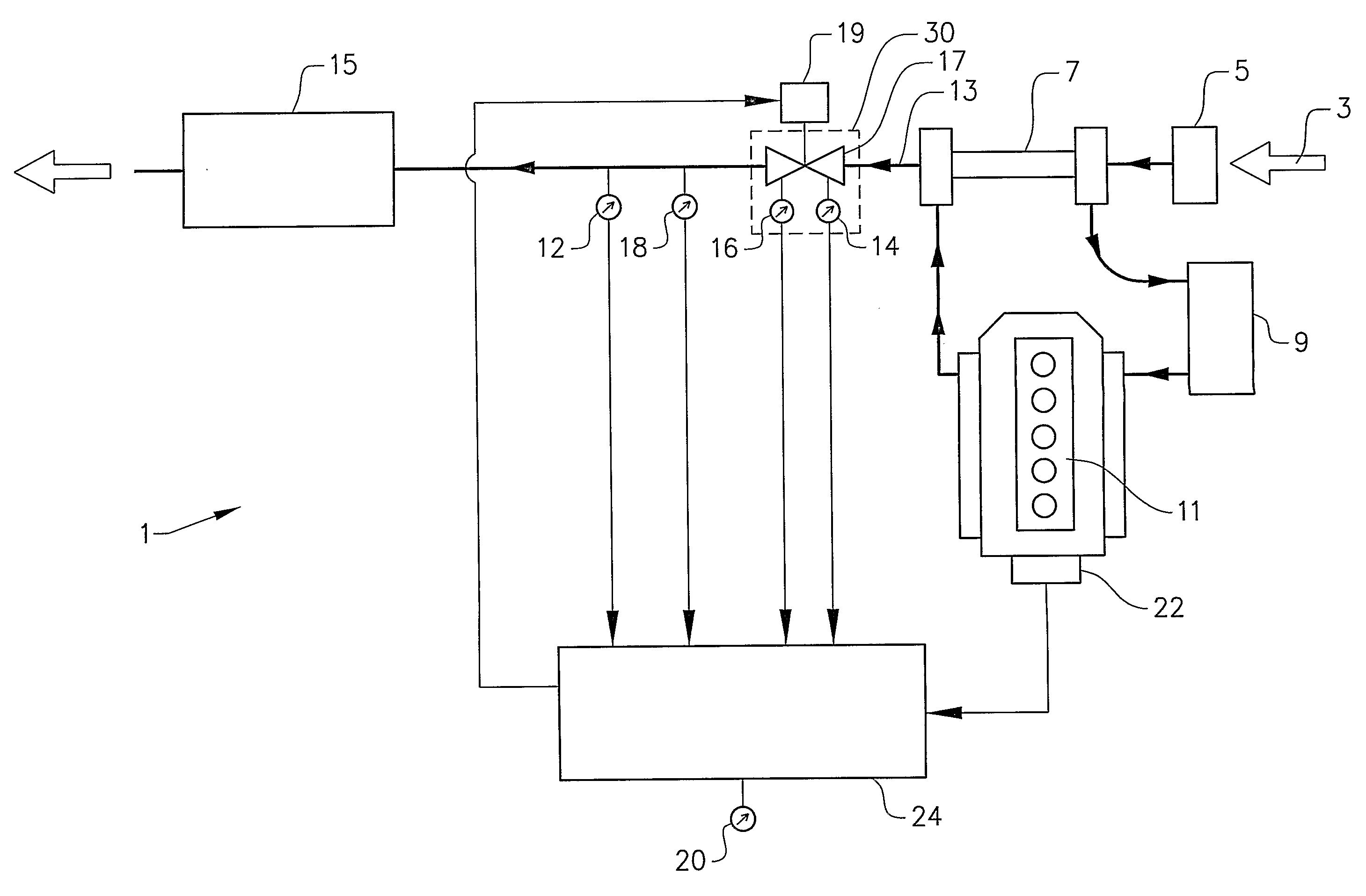
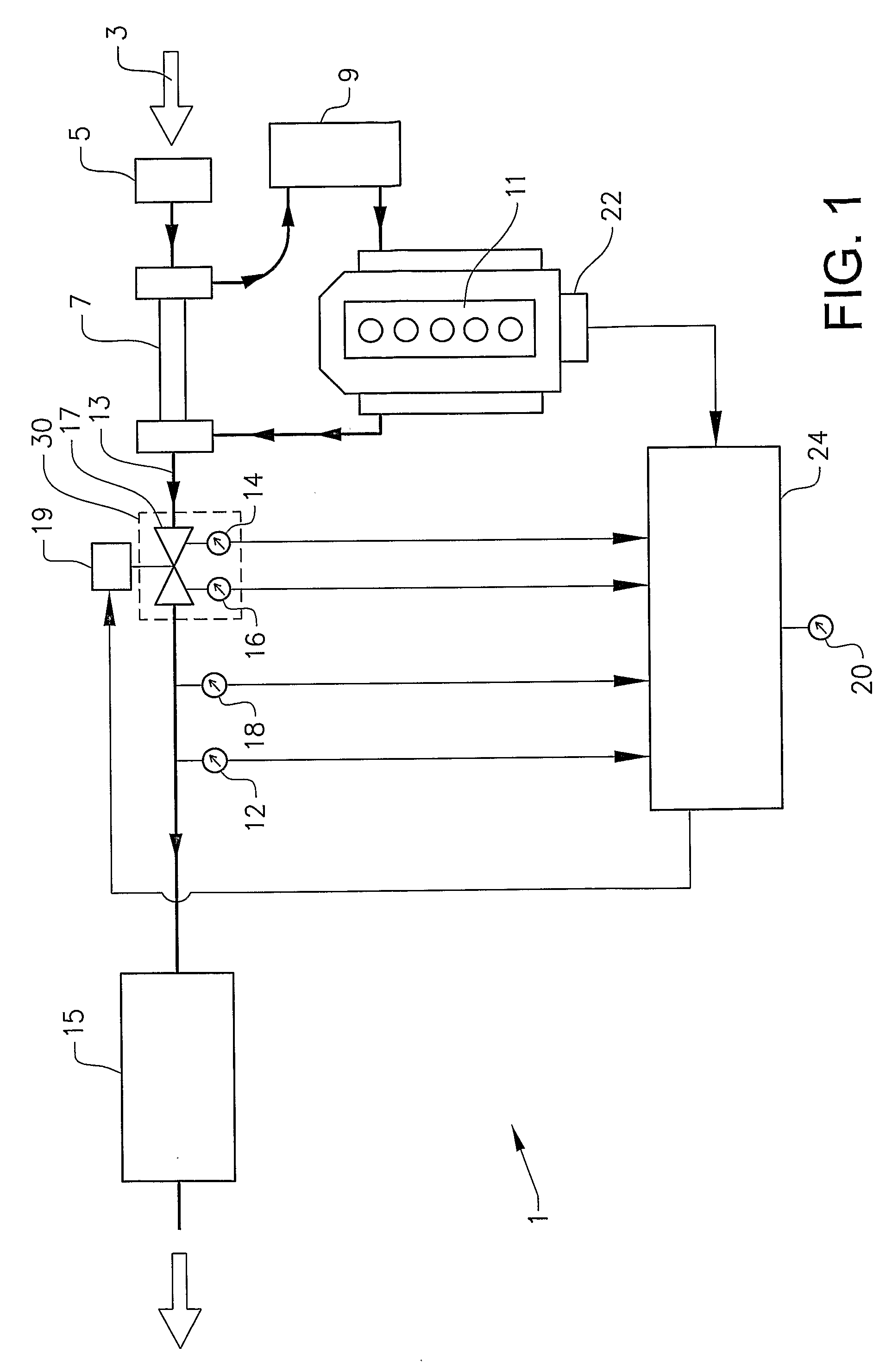
[0036]FIG. 1 shows, in a schematic view, an exhaust gas system 1 for treatment of an exhaust gas flow from an internal combustion engine according to a preferred embodiment of the invention. Air 3 passes an air filter 5, a turbo unit 7 and a cooler 9 on its way to a diesel engine 11. Exhaust gas leaving the engine 11 passes the turbo unit 7 and enters an exhaust gas conduit 13 whereby it passes a particulate filter 15 before it leaves the system. A gas flow control device 30, comprising an exhaust butterfly valve 17, is positioned in the exhaust gas conduit 13 upstream the filter 15. A valve operating actuator 19 is arranged to operate, i.e. to open and close, the exhaust valve 17.
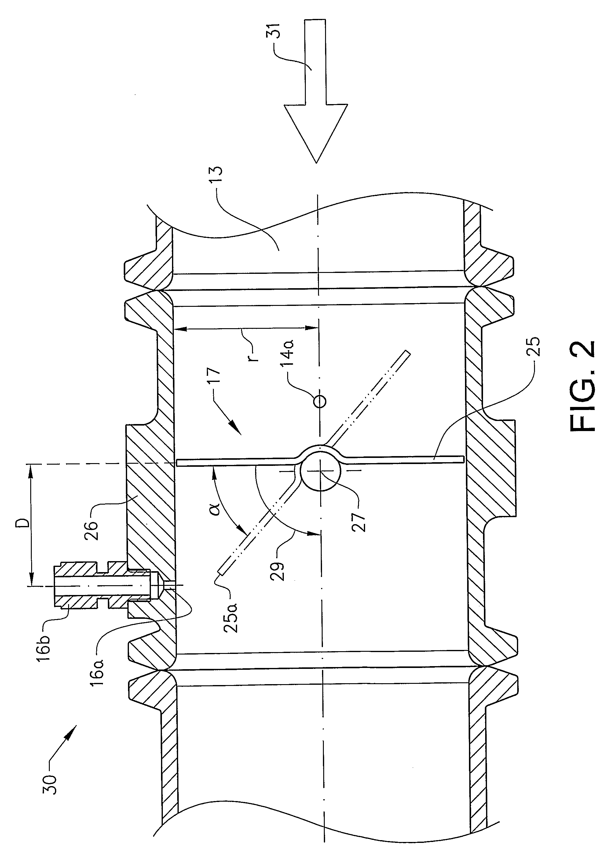
[0037]A first and a second pressure sensor 14, 16 are arranged in connection to the exhaust valve 17. These pressure sensors are further described with reference to FIG. 2. A temperature sensor 12 and a third pressure sensor 18 are arranged in the exhaust gas conduit 13 between the filter 15 and the exhaus...
PUM
 Abstract
Description
Claims
Application Information