
Method and device for changing a water level and use thereof in the separation of solids from liquids

a technology of water level and separation method, which is applied in the direction of water supply installation, water/sludge/sewage treatment, water supply valve type, etc., can solve the problems of affecting the separation capacity of the sieve structure, and excessively low tail water level, so as to increase the hydraulic throughput of the grate of other sieves or rakes, the effect of increasing the flow velocity at the channel sidewalls and increasing the hydraulic throughpu

Inactive Publication Date: 2015-09-24
RUDOLF BISCHOF TECHN HV ABWASSERTECHN
View PDF6 Cites 4 Cited by
  • Summary
  • Abstract
  • Description
  • Claims
  • Application Information

AI Technical Summary

Benefits of technology

The patent describes a method and device to increase the water level behind a sieve or rake arrangement in a channel. This leads to better solids retention and reduced deposit buildup. The device includes a damming body that can be adjusted to control the water level and flow velocity. Increasing the water level also increases the hydraulic throughput of the sieve or rake system. The technical effect of the patent text is to provide an improved method and device for controlling the water level in a channel with a sieve or rake arrangement.

Problems solved by technology

Due to the structural conditions in a wastewater treatment plant for example, the terrain directly behind the sieve or rake arrangement could be a downward slope, which causes a low tail water level.
An excessively low tail water level affects the separating capacity of the sieve structures.
On the other hand, if the level is high, deposits may build up in the head water region ahead of the sieve or rake system.
An excessively low tail water level in the flow direction behind the sieve or rake arrangement causes the following drawbacks.
As a result, the separating capacity of the sieve or rake device is diminished.
A drawback of a so-called Venturi constriction is however that deposits are built up in the head water region ahead of the sieve or rake arrangement.

Method used


Image

  • Method and device for changing a water level and use thereof in the separation of solids from liquids
  • Method and device for changing a water level and use thereof in the separation of solids from liquids
  • Method and device for changing a water level and use thereof in the separation of solids from liquids

Examples


Embodiment Construction

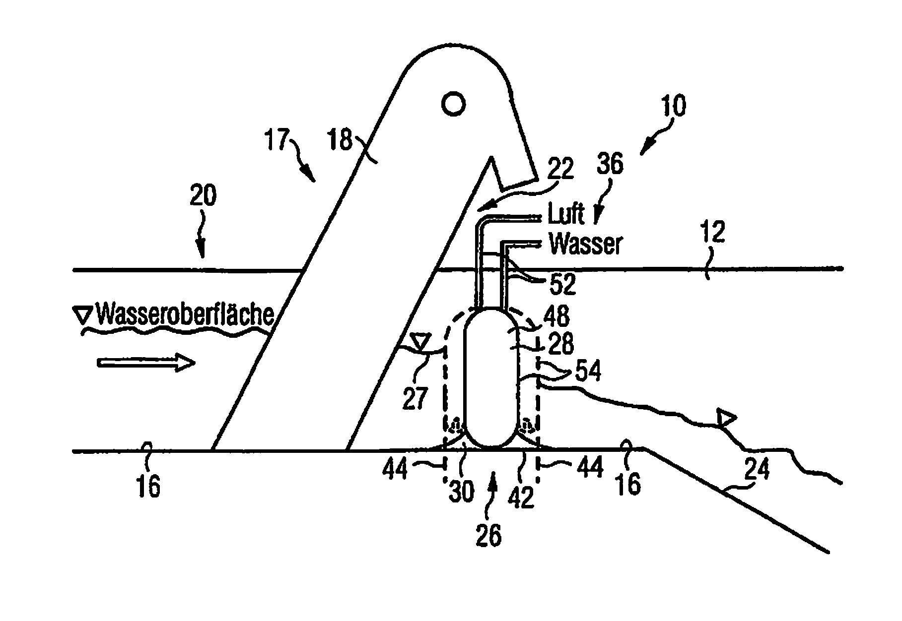
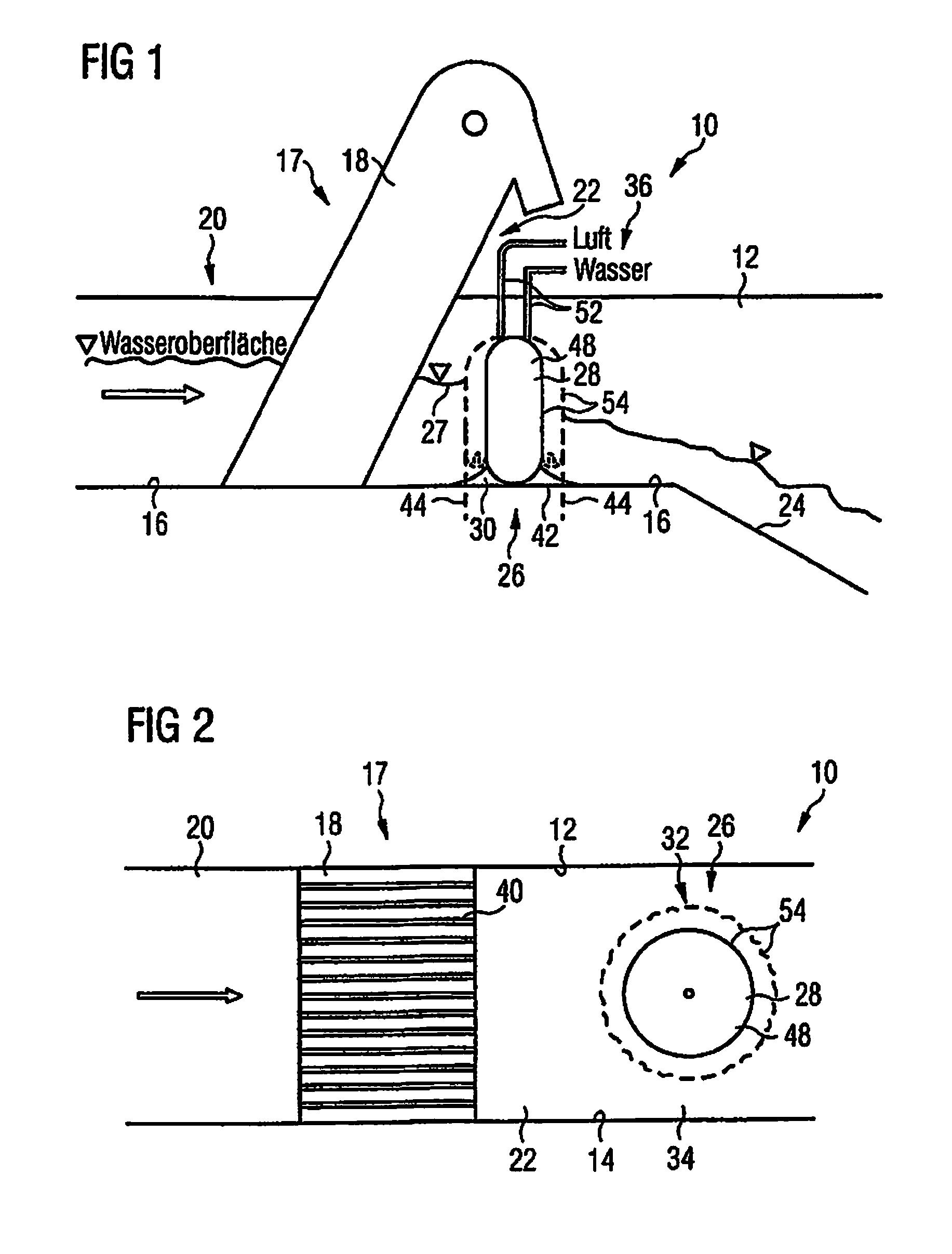
[0042]FIGS. 1 and 2 illustrate an example of a channel 10 used for conducting for example wastewater of a wastewater treatment plant not further shown. On the left and on the right said channel 10 is defined by sidewalls 12, 14 and on the lower side by a bottom 16.

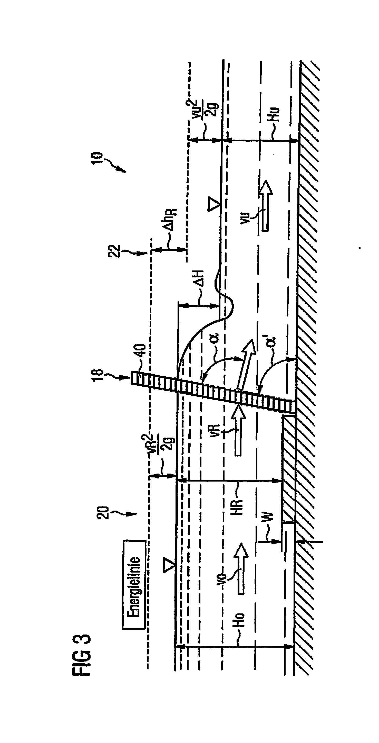
[0043]For separating out solids inflowing with the wastewater, a separation device 17 is provided at the channel 10. The separation device 17 includes a sieve or rake arrangement 18. As a sieve or rake arrangement 18 there is used for example a sieve rake device as disclosed in DE 10 2011 082 629 A1. The sieve or rake arrangement 18 accordingly comprises a sieve rake 40 having bars or a similar sieve device (e.g. a perforated sheet).

[0044]The region of the channel 10 in the flow direction ahead of the sieve or rake arrangement 18 is referred to as head water 20 and the region of the channel 10 in the flow direction behind the sieve or rake arrangement 18 is referred to as tail water 22. In the region of the tail water 22, ...


PUM

PropertyMeasurementUnit
Lengthaaaaaaaaaa
Lengthaaaaaaaaaa
Pressureaaaaaaaaaa

Abstract

A system and method for changing the water level in a channel in the region of a sieve or rake arrangement through which a liquid flows, to separate solids from said liquid. The system and method employ a damming body arranged in the flow direction behind the sieve or rake arrangement and laterally spaced from both channel sidewalls of the channel.

Description

CROSS-REFERENCE TO RELATED APPLICATION[0001]This application claims priority under 35 U.S.C. §119(a) to German Patent Application No. 10 2014 103 865.7, filed on Mar. 20, 2014, the entire contents of German Patent Application No. 10 2014 103 865.7 are hereby incorporated herein by reference.BACKGROUND[0002]1. Field of the Invention[0003]The invention relates to a method for changing a water level in a channel in the region of a sieve or rake arrangement. The invention further relates to a separation process for removing solids from a liquid flow using such a method for changing a water level. The invention also relates to a water level changing device for changing the water level in a channel. Finally, the invention relates to a separation device for separating solids from a liquid flow comprising such a water level changing device.[0004]2. Background Information[0005]An inflatable rubber dam inflatable by a pressurized agent for damming flumes or channels is described in DE 1 297 0...

Claims


Application Information

Patent Timeline
IPC IPC(8): G05D9/00C02F1/00
CPCC02F1/001G05D9/00E03F5/14E02B7/005Y10T137/0324Y10T137/7287
Inventor BISCHOF, RUDOLF
Owner RUDOLF BISCHOF TECHN HV ABWASSERTECHN
Learn More