Automobile hydraulic cylinder with self-locking function

A technology of hydraulic cylinder and function, applied in the field of automobile hydraulic cylinder, can solve the problems of soft leg phenomenon, easy leakage of hydraulic oil, negative pressure effect, etc., and achieve the effect of avoiding hydraulic oil leakage, avoiding negative pressure effect, and improving self-locking ability.

Inactive Publication Date: 2022-04-05
山东福阳液压科技有限公司
View PDF7 Cites 0 Cited by
  • Summary
  • Abstract
  • Description
  • Claims
  • Application Information

AI Technical Summary

Problems solved by technology

[0005] In order to solve the above-mentioned self-locking of the current hydraulic cylinder, it is mainly realized by blocking the pressure oil. However, the hydraulic oil in this locking method is easy to leak, and the problems of "negative pressure effect" and "soft leg phenomenon" will occur after the hydraulic oil leaks , the invention provides an automobile hydraulic cylinder with self-locking function

Method used


Image

  • Automobile hydraulic cylinder with self-locking function
  • Automobile hydraulic cylinder with self-locking function
  • Automobile hydraulic cylinder with self-locking function

Examples


Embodiment

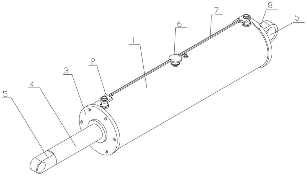
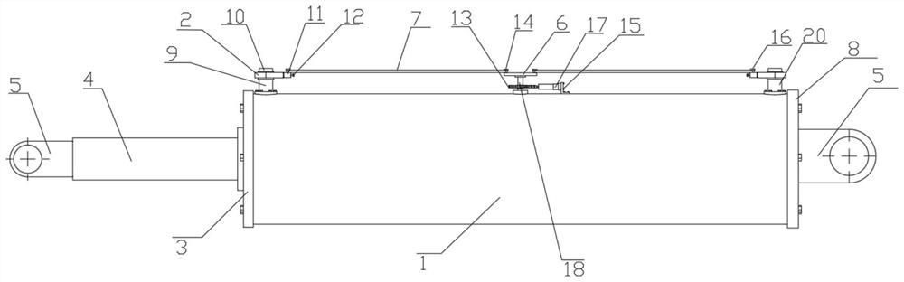
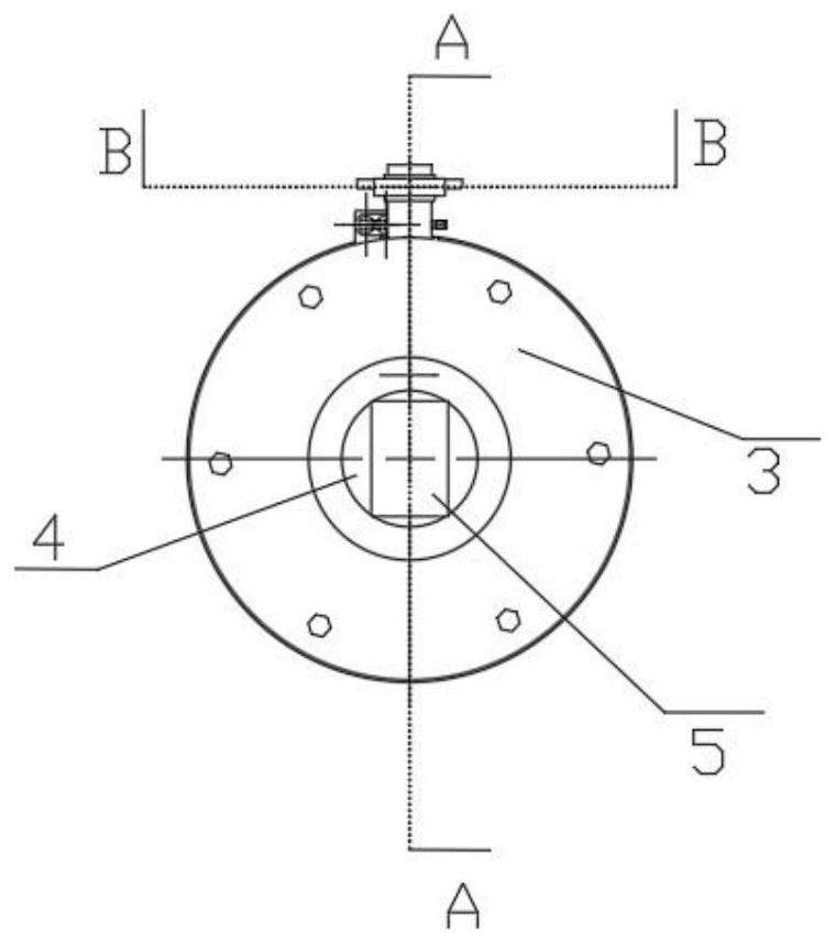
[0033] see Figure 5 with 7 As shown, a kind of automobile hydraulic cylinder with self-locking function comprises a hydraulic cylinder barrel 1, a cylinder cover 3 and a rear cylinder cover 8 are respectively arranged at both ends of the hydraulic cylinder cylinder barrel 1, and a first self-locking cylinder is provided on the inner wall of the rear cylinder cover 8. Lock structure, the first self-locking structure is connected with piston 36, and piston 36 is connected with cylinder rod 4, and cylinder rod 4 is slidingly matched with the movable hole that cylinder cover 3 offers, and cylinder rod 4 outer ends and rear cylinder cover 8 outer ends are all provided with Connecting seat 5, upper oil pipe 9 and lower oil pipe 20 are provided at both ends of the top of hydraulic cylinder barrel 1, lower oil pipe 20 is provided with first self-locking structure, second self-locking structure is evenly provided with connecting pipe 10, connecting pipe 10 and hydraulic pressure Oil ...

Embodiment 2

[0037] On the basis of embodiment 1, see Figures 1 to 8 As shown, the second self-locking structure includes a U-shaped plate 2, a first rotating plate 6, a second rotating plate 7, an adjustment assembly, a ring gear 13, a first rotating pin 14, a mounting base 15, and a second rotating pin 16 , electric push rod 17, rotating shaft 18, through hole 23, circular plate 22, first sliding plate 26 and U-shaped groove 35, U-shaped plate 2 is provided with U-shaped groove 35, and the inner wall of U-shaped groove 35 is slidably fitted with a circle plate 22, the middle end of the circular plate 22 is provided with a through hole 23, the side wall of the circular plate 22 is provided with a first sliding plate 26, the outer end of the first sliding plate 26 is connected with an adjustment assembly, and the adjustment assembly is provided with a second rotating pin 16 , the second rotating pin 16 rotates with a second rotating plate 7, and the second rotating plate 7 inner ends rota...

Embodiment 3

[0040] On the basis of embodiment 2, see figure 2 with 8 As shown, the adjustment assembly includes an adjustment sleeve 11 and an adjustment screw 12. The first sliding plate 26 is inserted in the adjustment sleeve 11. The outer end of the first sliding plate 26 rotates with an adjustment screw 12 through a bearing. The adjustment sleeve 11 is connected to the adjustment screw through a threaded sleeve 12 threaded connection, the bottom of the second rotating pin 16 is located at the top of the adjusting sleeve 11.

[0041] The adjusting screw 12 of the rotating adjusting assembly, the adjusting screw 12 drives the first sliding plate 26 to move in the adjusting sleeve 11, and the first sliding plate 26 drives the through hole 23 to move, which is convenient for adjusting the relative position of the circular plate 22 and the straight hole of the U-shaped plate 2 , it is convenient to adjust the hydraulic oil flow rate of the upper oil pipe 9 and the lower oil pipe 20, ther...


PUM


Abstract

The invention provides an automobile hydraulic cylinder with a self-locking function, belongs to the technical field of hydraulic transmission equipment, and solves the problems that self-locking of an existing hydraulic cylinder is mainly realized by means of blocking pressure oil, however, hydraulic oil is easy to leak in the locking mode, and a negative pressure effect and a soft leg phenomenon occur after the hydraulic oil leaks. According to the technical scheme, the hydraulic cylinder comprises a hydraulic cylinder barrel, the hydraulic cylinder barrel is provided with a cylinder cover and a rear cylinder cover, the rear cylinder cover is provided with a first self-locking structure, the first self-locking structure is provided with a piston, the piston is provided with a cylinder rod, the cylinder rod and the rear cylinder cover are provided with a connecting base, and the hydraulic cylinder barrel is provided with an upper oil pipe and a lower oil pipe. The self-locking hydraulic cylinder has the beneficial effects that self-locking of the cylinder rod is achieved, hydraulic oil leakage can be avoided, and the negative pressure effect and the soft leg phenomenon are avoided.

Description

technical field [0001] The invention relates to the technical field of hydraulic transmission equipment, in particular to an automobile hydraulic cylinder with a self-locking function. Background technique [0002] A hydraulic cylinder is a hydraulic actuator that converts hydraulic energy into mechanical energy and performs linear reciprocating motion (or swing motion). Hydraulic cylinders are one of the essential executive components in automobiles. [0003] According to work requirements, sometimes it is necessary for the hydraulic cylinder in the automobile to keep its position for a certain period of time after it moves to a certain position or after the hydraulic cylinder in the automobile stops working. In order to prevent the hydraulic cylinder in the automobile from being displaced under the action of external force, gravity and other forces , At this time, the hydraulic cylinder needs to be locked. At present, the self-locking of the hydraulic cylinder is mainly ...

Claims


Application Information

Patent Timeline
Patent Type & Authority Applications(China)
IPC IPC(8): F15B15/26F15B15/14
Inventor 吕怀健杨绍安庞世伟冯起宋成凯杨诗舟武玉林徐以成
Owner 山东福阳液压科技有限公司
Why Eureka
Try Eureka