A method performed by a control unit for controlling energy flows of a vehicle

a technology of energy flow and control method, which is applied in the direction of engine-driven generators, machines/engines, transportation and packaging, etc., can solve the problems of increasing the difficulty of making large improvements in order to improve fuel efficiency, auxiliary systems such as air conditioning systems, power steering etc., consume a large portion, and the tuning process of the control method is time-consuming and complex

Active Publication Date: 2017-10-19
VOLVO LASTVAGNAR AB
View PDF6 Cites 4 Cited by
  • Summary
  • Abstract
  • Description
  • Claims
  • Application Information

AI Technical Summary

Benefits of technology

[0014]Herein the use of mechanical energy of the mechanical energy subsystem for providing propulsion of the vehicle is considered to be conversion of energy. Propulsion can be considered, to be conversion of mechanical energy to translational kinetic energy, for which the drivetrain, comprising drive shafts, transmission, wheels etc. can be considered to be the converter. Thus the drivetrain acts as a converter for converting mechanical energy from the mechanical energy subsystem to translational kinetic energy, or energy used for propulsion of the vehicle, provided to a propulsion energy subsystem. According to the present invention by controlling the energy flow to the propulsion energy subsystem it is possible to control the energy used for propulsion by the propulsion system.
[0050]According to yet one aspect of the present invention the second sample frequency is longer than said first sample frequency. As previously is stated the setting of unitary energy prices of respective energy subsystem and, based or set unitary energy prices, subsequently providing energy between respective energy subsystems is performed according to the first sample frequency by the control unit. Controlling the energy flows of an energy system of a vehicle by controlling how is provided between the energy subsystems is the purpose of the present invention. However, the setting of individual price limits, supporting how the energy transfers between energy subsystems should be performed, may be performed according to a longer sample frequency. The setting of price limits is important aspect of the present invention, but setting a longer sample frequency will not impair the functionality of the present invention. However, by setting a longer sample frequency for the updating of price limits for respective energy converter the overall computational power required by control unit when running the method of the present invention is lowered.

Problems solved by technology

The combustion engine and the powertrain has been refined for many years, and it is becoming more and more difficult to make large improvements in order to improve the fuel efficiency.
How much power that needs to be produced, where in the energy system and how this power should be consumed or stored is however far from trivial to determine.
There are many energy systems, components or functionalities of a vehicle that consume energy.
A significant portion of the available energy is naturally used for the propulsion of the vehicle but auxiliary systems such as air condition systems, vehicle compartment heating systems, power steering etc. also consume a large portion.
This makes the tuning process of the control method time consuming and complex, and since it is directly dependent on the present setup it needs to be redone at the slightest change of the setup.
Also, during acceleration when a number of auxiliary systems are running, such as at a takeover manoeuvre during a hot summer night, the driver cannot expect to always get the requested increase in engine output.
This may be something that drivers of heavy duty vehicles such as trucks or busses are used to but is still undesirable both from a driveability and safety perspective.
In principle, what has been described as a problem for heavy duty vehicles also applies for passenger cars even if the problem with insufficient engine output is less significant.
Thus, no real prioritization between important auxiliary systems and less important auxiliary systems, nor any assessment of if the propulsion of the vehicle perhaps should be prioritized, is performed.
The quantity of power provided is limited by power limitations of the common converter.
Correspondingly, ambient temperature, air humidity and sunny conditions may affect the vehicle compartment temperature, wet conditions may affect the windshield wipers.

Method used


Image

  • A method performed by a control unit for controlling energy flows of a vehicle
  • A method performed by a control unit for controlling energy flows of a vehicle
  • A method performed by a control unit for controlling energy flows of a vehicle

Examples


Embodiment Construction

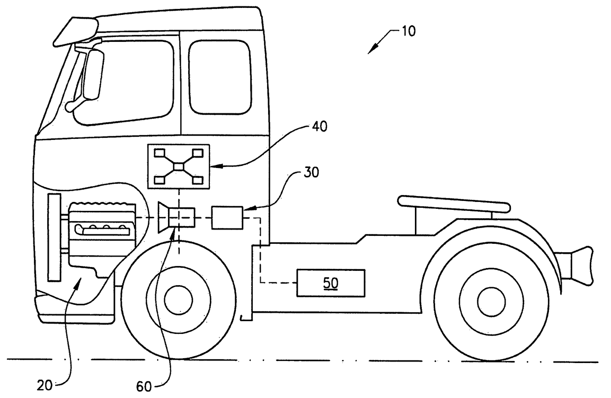
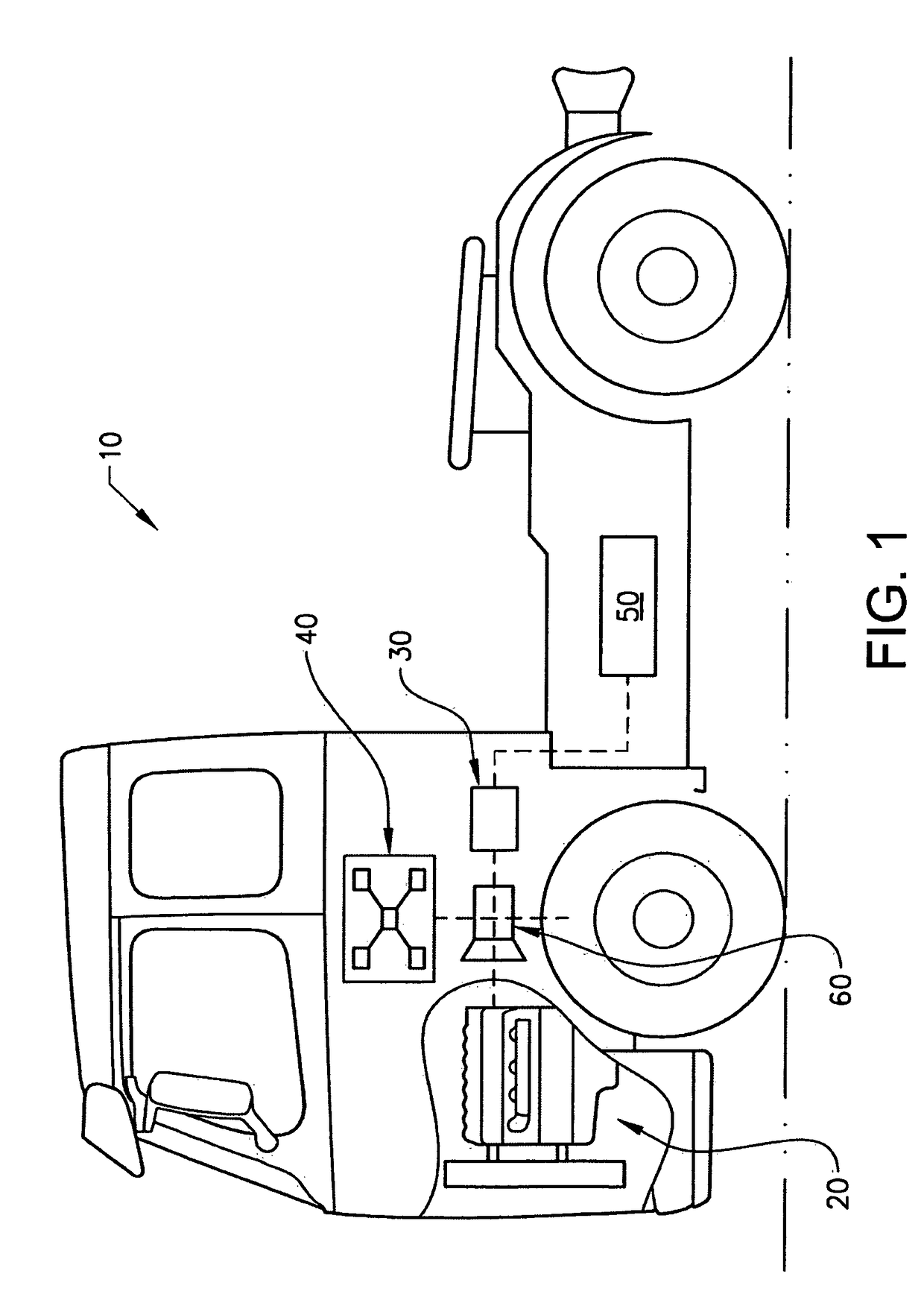
[0068]FIG. 1 discloses a schematic embodiment of a heavy duty hybrid vehicle 10 comprising an internal combustion engine (ICE) 20, a converter in form of an electric machine 30, an energy buffer 50 in form of an electrical battery, a drivetrain 60 and a control unit 40 for controlling energy flows of said heavy duty hybrid vehicle 10. The electrical battery energy buffer 50 is connected to the ICE 20 via the electric machine converter 30 and the drivetrain 60. The control unit 40 is provided such that the ICE 20, the electric machine converter 30, the drivetrain 60 and the electrical battery energy buffer 50 can be controlled by the control unit 60. The method of the present in Mention is performed by the control unit 40 and is suitable to apply for the vehicle 10. In the embodiment of the present invention disclosed in FIG. 1 the control unit 40 is schematically depicted as one physical component. However, as is obvious for a person skilled in the art, the control unit 40 may also ...


PUM


Abstract

In a method performed by a control unit for controlling energy flows of a vehicle, where the vehicle includes a vehicle energy system which in turn includes a plurality of energy subsystems. Within each energy subsystem one form of energy is used. The energy subsystems are operationally connected by converters, wherein converters are devices converting at least one form of energy to another form of energy. By setting a price, limits for the converters converting energy between the energy subsystem the energy flows of the vehicle can be controlled by the control unit such that at least during period of times the order in which the energy subsystems of the vehicle is provided with energy can be changed.

Description

BACKGROUND AND SUMMARY[0001]The present invention relates to the field of methods for managing energy flows within an energy system of a vehicle. The invention can be applied in heavy-duty vehicles such as trucks and busses, as well as for other type of vehicles such as passenger cars.[0002]Due to increasingly stringent legislation and an increasing interest from the market fuel efficiency has been one of the main drivers for passenger cars for many years. However, today fuel efficiency is one of the main drivers not only for passenger cars but also for heavy duty vehicles and other commercial vehicles. The combustion engine and the powertrain has been refined for many years, and it is becoming more and more difficult to make large improvements in order to improve the fuel efficiency. Instead all aspects of the engine, the powertrain and the control functionalities have to be considered. All small improvements, especially if the improvement can be achieved without adding substantial...

Claims


Application Information

Patent Timeline
Patent Type & Authority Applications(United States)
IPC IPC(8): B60W20/15B60W30/188B60L50/16F03G7/00
CPCB60W20/15B60W30/1886F03G7/00B60W2550/12Y10S903/904B60W2900/00B60W10/06B60W10/30B60W30/188Y02T10/84Y02T10/40B60W2555/20
Inventor ASKERDAL, MIKAELASBOGARD, MATTIAS
Owner VOLVO LASTVAGNAR AB
Why Eureka
Try Eureka