Method and data processing device for determining a spacing of rolling elements

a data processing device and spacing technology, applied in mechanical equipment, instruments, force/torque/work measurement apparatus, etc., can solve the problem that the computational power of microcontrollers configured to be integrated into or attached to bearings is very limited, and achieve the effect of reliable and simple monitoring

Active Publication Date: 2020-02-18
AB SKF
View PDF15 Cites 0 Cited by
  • Summary
  • Abstract
  • Description
  • Claims
  • Application Information

AI Technical Summary

Benefits of technology

[0007]The invention seeks to provide a reliable and simple way to monitor the roller spacing and the cage integrity.
[0008]The method of the invention seeks to determine roller spacings (gaps) from Roller Load Induced Strain (RLIS) signals measured by a preferably wireless node on one of the rings of a large size bearing. Microcontrollers in wireless nodes configured to be integrated into or attached to a bearing have very limited computational power. A further object of the invention is therefore to provide a method simple enough to be implemented in the node rather than in a remote server receiving the raw strain signals from the node.

Problems solved by technology

Microcontrollers in wireless nodes configured to be integrated into or attached to a bearing have very limited computational power.

Method used


Image

  • Method and data processing device for determining a spacing of rolling elements
  • Method and data processing device for determining a spacing of rolling elements
  • Method and data processing device for determining a spacing of rolling elements

Examples


Embodiment Construction

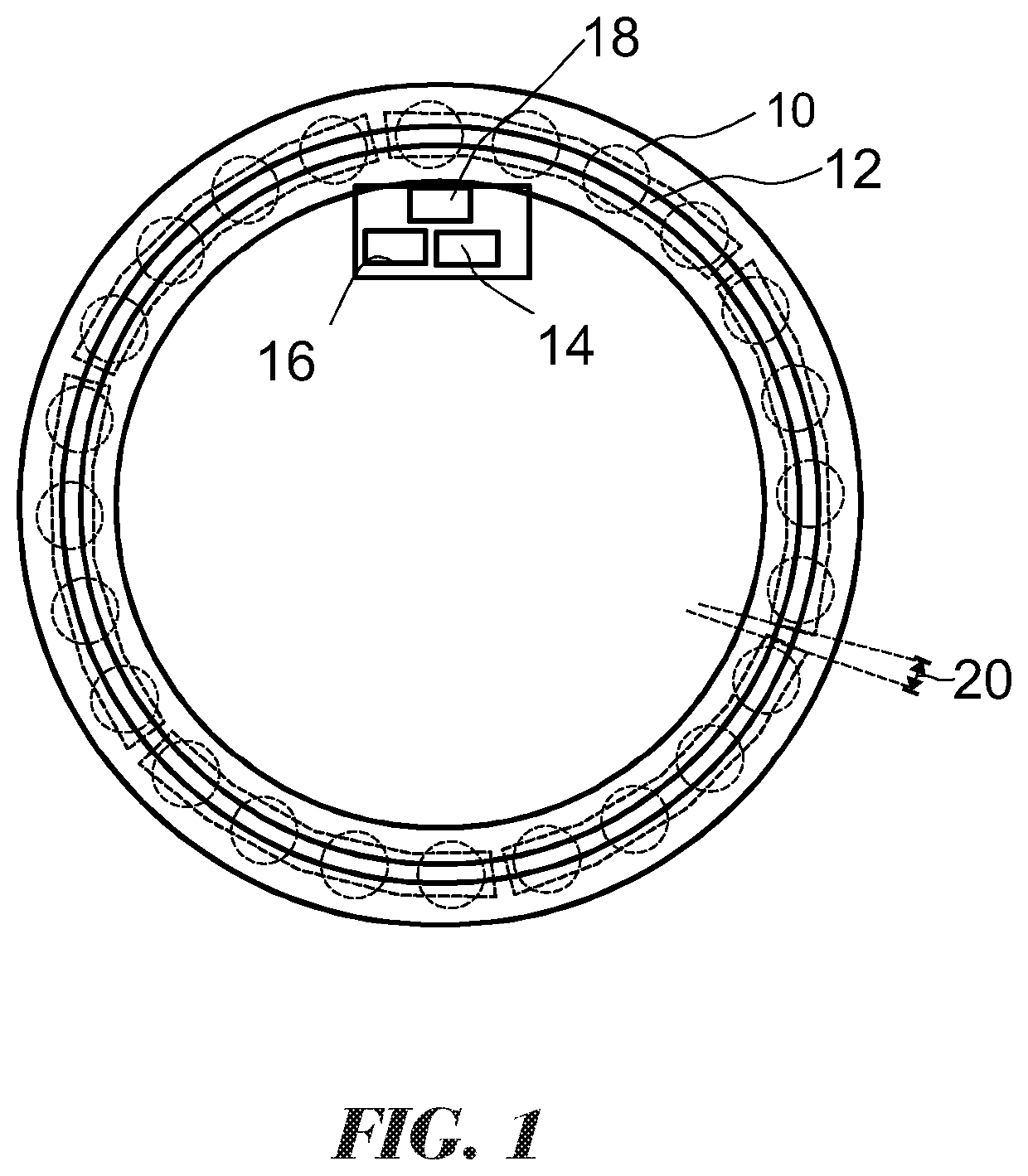
[0034]FIG. 1 is a schematic representation of the roller bearing including 24 rollers 10 arranged in 6 cages 12, wherein each of the cages 12 holds four rollers 10. A strain sensor 14 is attached to or embedded into an inner ring of the bearing and connected to the input of a data processing device 16 formed as a microcontroller.

[0035]The invention is applicable to configurations with more than one sensor, in particular with three or four sensors arranged on the inner ring or to applications where the sensor 14 is mounted on the outer ring.

[0036]The microcontroller is configured to drive a wireless transmitter mounted in the same electronics pack. Preferably, the electronics pack includes a power harvesting means (not illustrated) for generating power from the rotation of the bearing.

[0037]The six cages 12 of the bearing are designed so as to be arranged with a predetermined spacing or gap 20 in between each pair of adjacent cages 12. The distribution of the gaps 20 is subject to dy...


PUM


Abstract

A method for detecting roller spacings in a roller bearing having at least one row of rollers wherein the rollers in the row are held by at least one cage, preferably by a plurality of roller cages. The method uses roller load induced strain signals for determining the roller spacings.

Description

CROSS REFERENCE TO RELATED APPLICATION[0001]This is a Non-Provisional Patent Application, filed under the Paris Convention, claiming the benefit of Great Britain (GB) Patent Application Number 1418059.0, filed on 13 Oct. 2014, which is incorporated herein by reference in its entirety.BACKGROUND OF THE INVENTION[0002]Large size bearings e.g. for supporting rotors of wind turbines are generally too large for a single cage to hold the rollers. The bearings are therefore often designed with a plurality of individual roller cages holding e.g. one or two rollers per cage or with numerous cage segments that hold four rollers each. There is by design a nominal clearance to allow for thermal expansions which can be distributed or can accumulate in one location, which is acceptable. However if any cage segment is broken up then the roller spacings can go out with the design minimum and maximum tolerances.[0003]Known methods of assessing the roller spacing or the cage integrity are based on vi...

Claims


Application Information

Patent Timeline
Patent Type & Authority Patents(United States)
IPC IPC(8): G01M13/04G01B7/14G01M13/045
CPCG01B7/14G01M13/045G01M13/04F16C19/52F16C19/522G01L5/0019
Inventor THOMSON, ALLAN
Owner AB SKF
Why Eureka
Try Eureka